C. Connect Ground (GND) to Ground (GND).
D.MIC_RET and OUT_RET are for HD audio panel only. You don’t need to connect them for AC’97 audio panel.
E.Enter BIOS Setup Utility. Enter Advanced Settings, and then select Chipset Configuration. Set the Front Panel Control option from [Auto] to [Enabled].
F.Enter Windows system. Click the icon on the lower right hand taskbar to enter Realtek HD Audio Manager.
For Windows® XP / XP
Click “Audio I/O”, select “Connector Settings” ![]() , choose “Disable front panel jack detection”, and save the change by clicking “OK”.
, choose “Disable front panel jack detection”, and save the change by clicking “OK”.
For Windows® VistaTM / VistaTM |
|
Click the | , choose “Disable front |
panel jack detection”, and save the change by clicking “OK”. G. To activate the front mic.
For Windows® XP / XP
Please select “Front Mic” as default record device.
If you want to hear your voice through front mic, please deselect "Mute" icon in “Front Mic” of “Playback” portion.
For Windows® VistaTM / VistaTM
Go to the "Front Mic" Tab in the Realtek Control panel.
Click "Set Default Device" to make the Front Mic as the default record device.
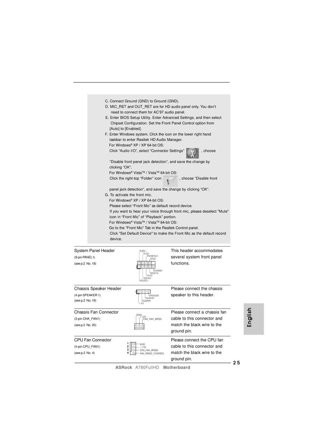
System Panel Header | This header accommodates |
several system front panel | |
(see p.2 No. 18) | functions. |
Chassis Speaker Header |
| Please connect the chassis | |
| speaker to this header. | ||
(see p.2 No. 19) |
|
| |
|
|
| |
Chassis Fan Connector |
| Please connect a chassis fan | |
| cable to this connector and | ||
(see p.2 No. 20) |
| match the black wire to the | |
|
| ground pin. | |
|
|
| |
CPU Fan Connector | 1 | Please connect the CPU fan | |
cable to this connector and | |||
2 | |||
(see p.2 No. 4) | 3 | match the black wire to the | |
4 |
ground pin. | 2 5 |
|
English
ASRock A780FullHD Motherboard