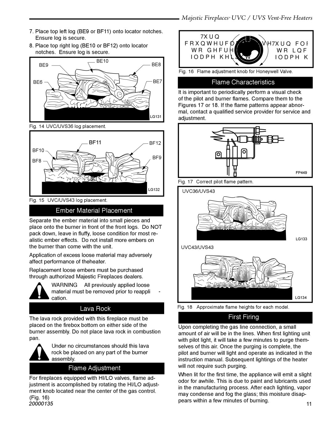
7.Place top left log (BE9 or BF11) onto locator notches. Ensure log is secure.

8.Place top right log (BE10 or BF12) onto locator notches. Ensure log is secure.

BE9

BE10

BE8


BE6


BE7

LG131

Fig. 14 UVC/UVS36 log placement.

BF11BF12

BF10

BF8 BF9

LG132

Fig. 15 UVC/UVS43 log placement.

Ember Material Placement

Separate the ember material into small pieces and place onto the burner in front of the front logs. Do NOT pack down, leave in fluffy, loose condition for most re- alistic ember effects. Do not install more embers on the burner than come with the unit.

Application of excess loose material may adversely affect performance of theheater.

Replacement loose embers must be purchased through authorized Majestic Fireplaces dealers.

WARNING: All previously applied loose material must be removed prior to reappli- cation.

Lava Rock

The lava rock provided with this fireplace must be placed on the firebox bottom on either side of the burner assembly. Do not place lava rock in combustion pan.

Under no circumstances should this lava rock be placed on any part of the burner assembly.

Flame Adjustment

For fireplaces equipped with HI/LO valves, flame ad- justment is accomplished by rotating the HI/LO adjust- ment knob located near the center of the gas control. (Fig. 16)

20000135

Majestic Fireplaces® UVC / UVS Vent-Free Heaters

Turn


counterclockwise

LO

HI

Turn clockwise

to decrease


to increase


flame height


flame height

Fig. 16 Flame adjustment knob for Honeywell Valve.

Flame Characteristics

It is important to periodically perform a visual check of the pilot and burner flames. Compare them to the Figures 17 or 18. If the flame patterns appear abnor- mal, contact a qualified service provider for service and adjustment.

FP449

Fig. 17 Correct pilot flame pattern.

UVC36/UVS43

LG133

UVC43/UVS43

LG134

Fig. 18 Approximate flame heights for each model.

First Firing

Upon completing the gas line connection, a small amount of air will be in the lines. When first lighting unit with pilot light, it will take a few minutes to purge them- selves of this air. Once the purging is complete, the pilot and burner will light and operate as indicated in the instruction manual. Subsequent lightings of the heater will not require such purging.

When lit for the first time, the appliance will emit a slight odor for awhile. This is due to paint and lubricants used in the manufacturing process. After each lighting, vapor

may condense and fog the glass; this moisture disap-


pears within a few minutes of burning.

11


Page 11
Image 11
CFM UVS36, UVC36, UVC43, UVS43 Ember Material Placement, Lava Rock, Flame Adjustment, Flame Characteristics, First Firing

UVC43, UVC36, UVS36, UVS43 specifications

CFM International has made significant advancements in the field of avionics with its cutting-edge line of aircraft engines, including the CFM UVS43, UVS36, UVC36, and UVC43 models. These engines are designed to enhance performance, reliability, and efficiency, catering to a broad spectrum of aviation needs.

The CFM UVS43 is engineered for high-performance applications, offering exceptional thrust and fuel efficiency. Its advanced materials and aerodynamic design allow for reduced weight and increased durability. The UVS43 employs state-of-the-art technologies, including a full-authority digital engine control (FADEC) system which optimizes engine performance by intelligently adjusting parameters in real-time.

Similarly, the UVS36 model is known for its versatility and adaptability in various aviation platforms. The engine incorporates a unique dual-spool design that provides improved efficiency at different altitudes and speeds. The UVS36 is equipped with advanced noise reduction technologies, ensuring compliance with stringent environmental regulations without compromising on performance.

The CFM UVC36 is another standout in the CFM engine lineup, designed specifically for regional aircraft. It features a compact design that allows for easy integration into smaller airframes while providing reliable thrust and performance. The UVC36 employs innovative cooling technologies that enhance engine longevity and reduce maintenance intervals, making it an attractive option for operators concerned with operational costs.

On the other hand, the UVC43 is tailored for larger aircraft, offering increased power output and efficiency. This model utilizes advanced composite materials, allowing for a lighter engine that still delivers exceptional performance. The UVC43 is also notable for its improved fuel consumption rates compared to previous models, thanks to its advanced turbine and combustion chamber design.

All four engine models share a commitment to sustainability, featuring reduced emissions and noise levels while enhancing operational efficiency. The integration of cutting-edge computer modeling and simulation techniques during the design phase has contributed to optimized performance across all models. With their combination of innovation, flexibility, and reliability, the CFM UVS43, UVS36, UVC36, and UVC43 engines represent the future of aviation powerplants, meeting the demanding requirements of modern air transport while ensuring a reduced environmental footprint. As aviation continues to evolve, CFM remains at the forefront, driving advancements that shape the industry.