C&H Technologies, Inc. <> 445 Round Rock West Drive <> Round Rock, TX 78681 <> www.chtech.com
APPENDIX A: CONNECTORS
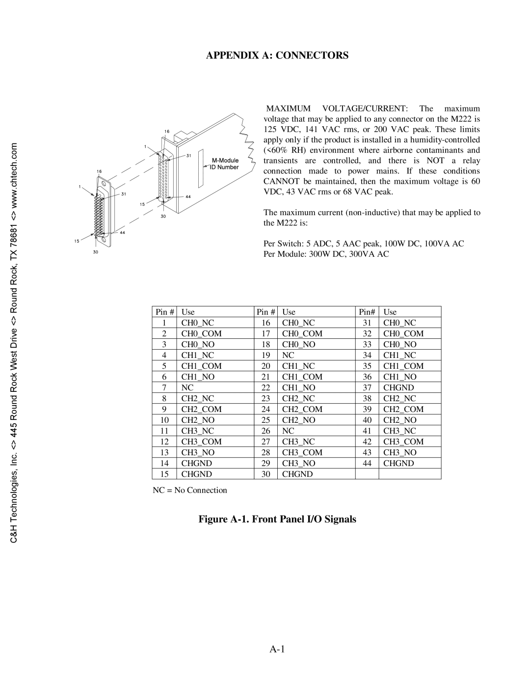
MAXIMUM VOLTAGE/CURRENT: The maximum voltage that may be applied to any connector on the M222 is 125 VDC, 141 VAC rms, or 200 VAC peak. These limits apply only if the product is installed in a
The maximum current
Per Switch: 5 ADC, 5 AAC peak, 100W DC, 100VA AC
Per Module: 300W DC, 300VA AC
Pin # | Use | Pin # | Use | Pin# | Use |
1 | CH0_NC | 16 | CH0_NC | 31 | CH0_NC |
2 | CH0_COM | 17 | CH0_COM | 32 | CH0_COM |
3 | CH0_NO | 18 | CH0_NO | 33 | CH0_NO |
4 | CH1_NC | 19 | NC | 34 | CH1_NC |
5 | CH1_COM | 20 | CH1_NC | 35 | CH1_COM |
6 | CH1_NO | 21 | CH1_COM | 36 | CH1_NO |
7 | NC | 22 | CH1_NO | 37 | CHGND |
8 | CH2_NC | 23 | CH2_NC | 38 | CH2_NC |
9 | CH2_COM | 24 | CH2_COM | 39 | CH2_COM |
10 | CH2_NO | 25 | CH2_NO | 40 | CH2_NO |
11 | CH3_NC | 26 | NC | 41 | CH3_NC |
12 | CH3_COM | 27 | CH3_NC | 42 | CH3_COM |
13 | CH3_NO | 28 | CH3_COM | 43 | CH3_NO |
14 | CHGND | 29 | CH3_NO | 44 | CHGND |
15 | CHGND | 30 | CHGND |
|
|
NC = No Connection