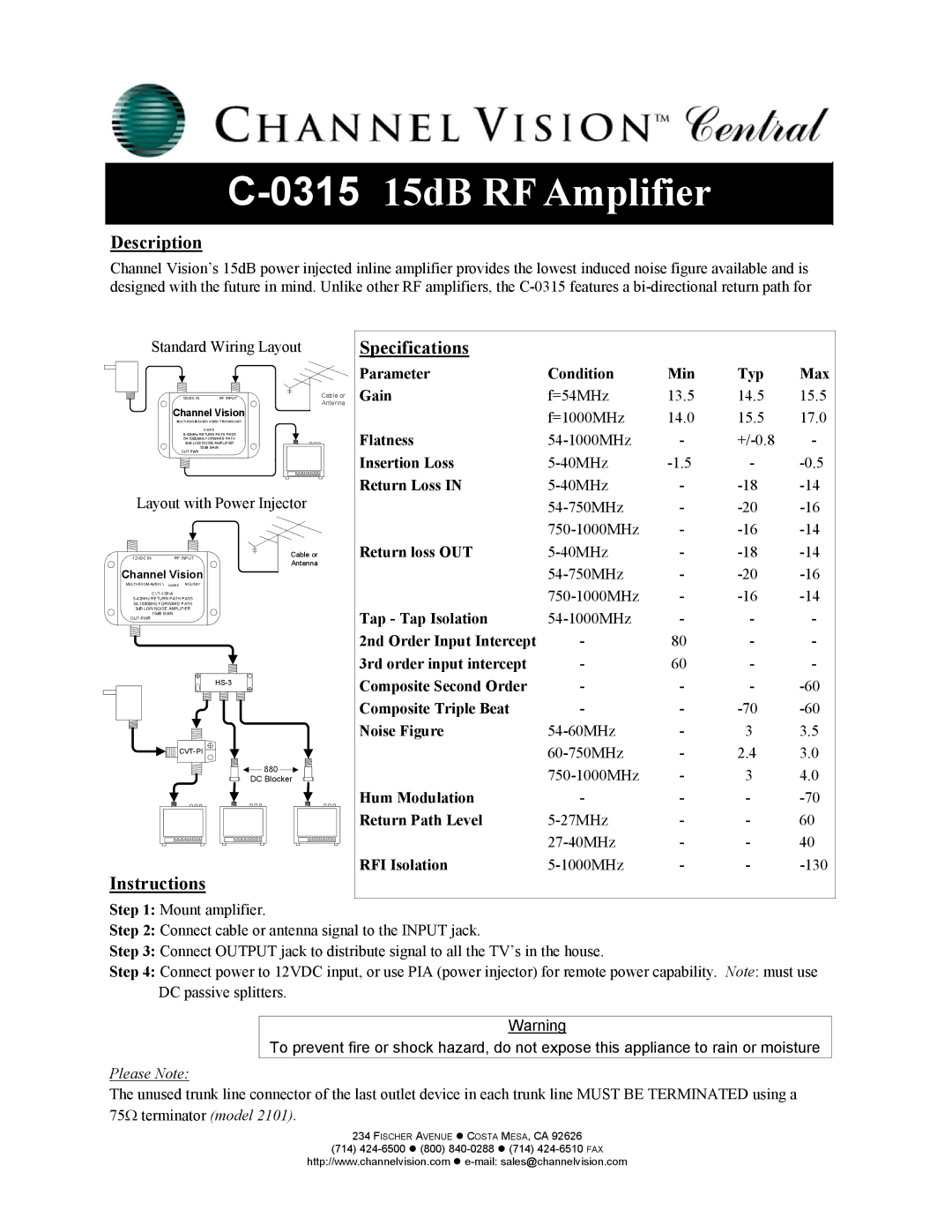
C-0315 specifications
The Channel Vision C-0315 is a highly regarded intercom system that is designed to seamlessly integrate with modern home automation and communication needs. This multi-zone intercom system stands out for its versatility, allowing users to communicate effectively while managing audio distribution throughout different areas of a home or facility.One of the main features of the C-0315 is its support for a multi-room audio system. It allows users to distribute sound from various sources, such as CD players, radios, and streaming devices, to different zones within a home. With the ability to connect up to 15 zones, it provides extensive coverage and flexibility for audio management. Users can control the audio in each zone independently, ensuring that everyone can enjoy their preferred sound experience in different areas.
In terms of user interface, the C-0315 boasts an intuitive keypad interface that simplifies operation. The system integrates well with other Channel Vision products, enhancing its functionality for a comprehensive audio-visual experience. The intercom's compatibility with other devices allows for centralized control and easy access, making it suitable for both residential and commercial environments.
The technology behind the C-0315 includes advanced audio transmission methods that ensure high-quality sound without interruption. It employs either wired or wireless connections, providing flexibility in installation based on the specific layout and requirements of the space. The system's digital signal processing capabilities further enhance audio clarity, contributing to an outstanding listening experience.
Another noteworthy characteristic of the Channel Vision C-0315 is its durability and sleek design. The unit is crafted with longevity in mind, ensuring that it withstands the test of time while maintaining an aesthetic appeal. It is also designed to be straightforward to install, making it appropriate for both DIY enthusiasts and professional installers.
Overall, the Channel Vision C-0315 intercom system combines advanced technology, user-friendly features, and reliable performance. It represents a smart choice for those seeking an efficient and expandable solution for multi-room audio and intercom communication, enhancing the overall convenience and functionality of modern living spaces.