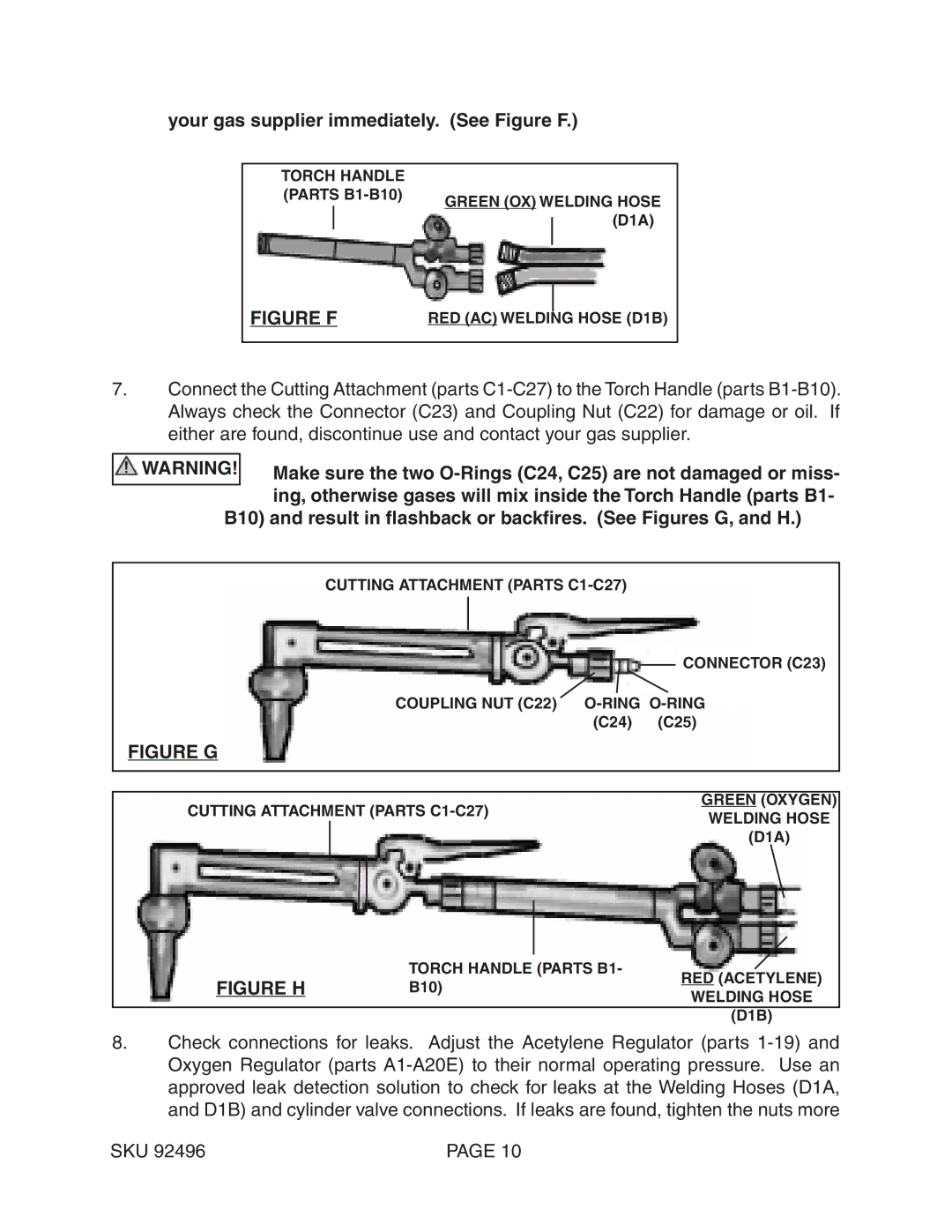
your gas supplier immediately. (See Figure F.)
TORCH HANDLE
(PARTS
FIGURE F |
|
|
RED (AC) WELDING HOSE (D1B) | ||
7.Connect the Cutting Attachment (parts
WARNING! | Make sure the two |
| ing, otherwise gases will mix inside the Torch Handle (parts B1- |
B10) and result in flashback or backfires. (See Figures G, and H.) | |
|
|
| CUTTING ATTACHMENT (PARTS |
CONNECTOR (C23)
COUPLING NUT (C22)
(C24) | (C25) |
FIGURE G
GREEN (oxygen)
CUTTING ATTACHMENT (PARTS
FIGURE H | TORCH HANDLE (PARTS B1- | RED (acetylene) | |
B10) | |||
WELDING HOSE | |||
|
| ||
|
| (D1B) |
8.Check connections for leaks. Adjust the Acetylene Regulator (parts
SKU 92496 | PAGE 10 |