Installation Instructions |
|
|
|
| TA410 | |
Installation |
|
|
|
|
| |
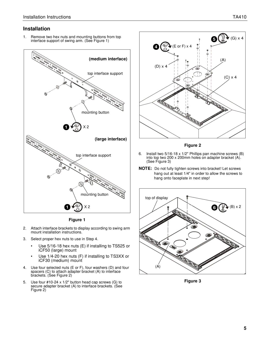
1. Remove two hex nuts and mounting buttons from top |
|
| 5 | (G) x 4 | ||
| interface support of swing arm. (See Figure 1) |
|
| |||
|
|
|
| 4 | (E or F) x 4 |
|
|
| (medium interface) |
|
|
| (A) |
|
|
|
| (D) x 4 |
|
|
|
| top interface support |
|
|
| (C) x 4 |
|
|
|
|
|
| |
|
| mounting button |
|
|
|
|
| 1 | X 2 |
|
|
|
|
|
| (large interface) |
|
|
|
|
|
|
|
|
| Figure 2 |
|
|
| top interface support | 6. | Install two | ||
|
|
| into top two 200 x 200mm holes on adapter bracket (A). | |||
|
|
|
| |||
|
|
|
| (See Figure 3) |
|
|
|
|
| NOTE: Do not fully tighten screws into bracket! Let screws | |||
|
|
|
| hang out at least 1/4" in order to allow the screws to | ||
|
|
|
| hang onto faceplate in next step! |
| |
|
| mounting button |
| top of display |
|
|
|
|
|
|
|
| |
| 1 | X 2 |
|
| 6 | (B) x 2 |
| Figure 1 |
|
|
|
| |
2. | Attach interface brackets to display according to swing arm |
|
|
|
| |
| mount installation instructions. |
|
|
|
| |
3. Select proper hex nuts to use in Step 4. |
|
|
|
| ||
| • Use |
|
|
|
| |
| iCF50 (large) mount |
|
|
|
| |
| • Use |
|
|
|
| |
| iCF30 (medium) mount |
|
|
|
| |
4. Use four selected nuts (E or F), four washers (D) and four |
| (A) |
|
| ||
| spacers (C) to attach adapter bracket (A) to interface |
|
|
|
| |
| brackets. (See Figure 2) |
|
|
|
|
|
5. Use four | Figure 3 |
secure adapter bracket (A) to interface brackets. (See |
|
Figure 2) |
|
5