CM2L40 specifications
The Chief Manufacturing CM2L40 is an exemplary product in the realm of LCD and plasma display mounting solutions, designed particularly for commercial and institutional environments. This mount stands out for its robust construction and versatile functionality, catering to a wide range of television sizes and weight capacities.One of the standout features of the CM2L40 is its exceptional weight capacity, supporting displays up to 400 pounds. This makes it ideal for mounting larger screens that are often required in professional settings such as conference rooms, classrooms, and public venues. The mount’s sturdy design ensures that it can hold heavy displays securely, providing peace of mind for users.
The CM2L40 is engineered with versatility in mind. It offers a variety of mounting options, including fixed, tilting, and full-motion capabilities. This adaptability allows users to position their displays at optimal viewing angles, enhancing the overall viewing experience. The tilting feature is particularly beneficial in environments where viewers might be seated below the screen, as it helps reduce glare and provides a better line of sight.
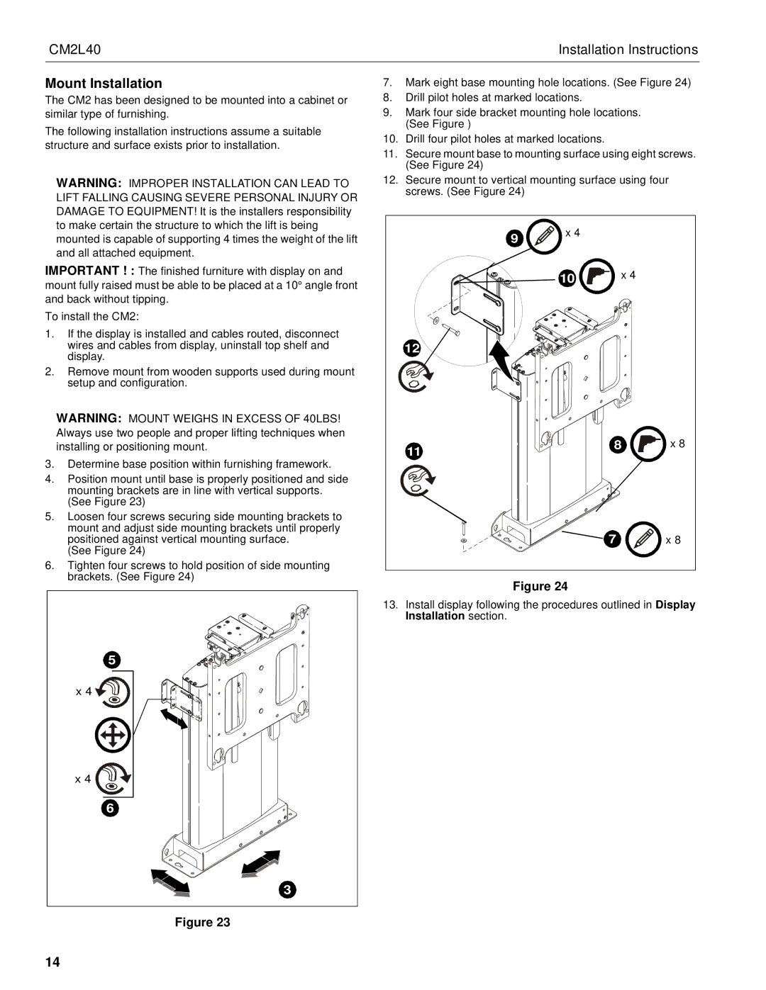
Installation of the CM2L40 is made simple with its user-friendly design. The mount includes a quick-release mechanism for easy access to the display, enabling effortless adjustments and maintenance. Additionally, the mount is compatible with various VESA patterns, offering flexibility for different screen brands and sizes.
A key technology used in the CM2L40 is its integrated cable management system. This feature helps to organize and conceal wiring, resulting in a cleaner and more professional appearance. By minimizing clutter, the mount contributes to a more aesthetically pleasing setup, which is essential in commercial environments.
Durability is another hallmark of the Chief Manufacturing CM2L40. Constructed from high-quality materials, it is designed to withstand the rigors of daily use in demanding environments. Its powder-coated finish not only enhances its visual appeal but also protects it from scratches and corrosion.
Overall, the Chief Manufacturing CM2L40 is an outstanding choice for anyone in need of a heavy-duty mount solution. Its combination of strength, versatility, and user-friendly features make it a smart investment for commercial applications, ensuring that display technology can be utilized effectively and stylishly. Whether for presentations, lectures, or digital signage, the CM2L40 provides a reliable platform for any large display need.

