Chief Manufacturing CM2L40 Installation Requirements, Power Requirements and Wiring

Models: CM2L40

1 76
Download 76 pages 43.64 Kb
Page 6
Image 6

CM2L40

Installation Instructions

INSTALLATION REQUIREMENTS

The CM2 has been designed to be mounted into a cabinet or similar type of furnishing.

WARNING: IMPROPER INSTALLATION CAN LEAD TO LIFT TIPPING CAUSING SEVERE PERSONAL INJURY OR DAMAGE TO EQUIPMENT! It is the installers responsibility to make certain the structure to which the lift is being mounted is capable of supporting 4 times the weight of the lift and all attached equipment.

Power Requirements and Wiring

The CM2 requires 120VAC (220/240VAC 50 Hz for European installations) power to operate.

A 6 ft long power cable is provided with the mount.

INSTALLATION

Pre-Installation Configuration and Adjustments

Prior to being installed, the CM2 requires the configuration of the mount for display, cable installation and routing, and the rough adjustment of the top cover mounting bracket.

To prepare the CM2 for Installation:

1.Remove mount from box.

2.Remove two wooden supports from under box.

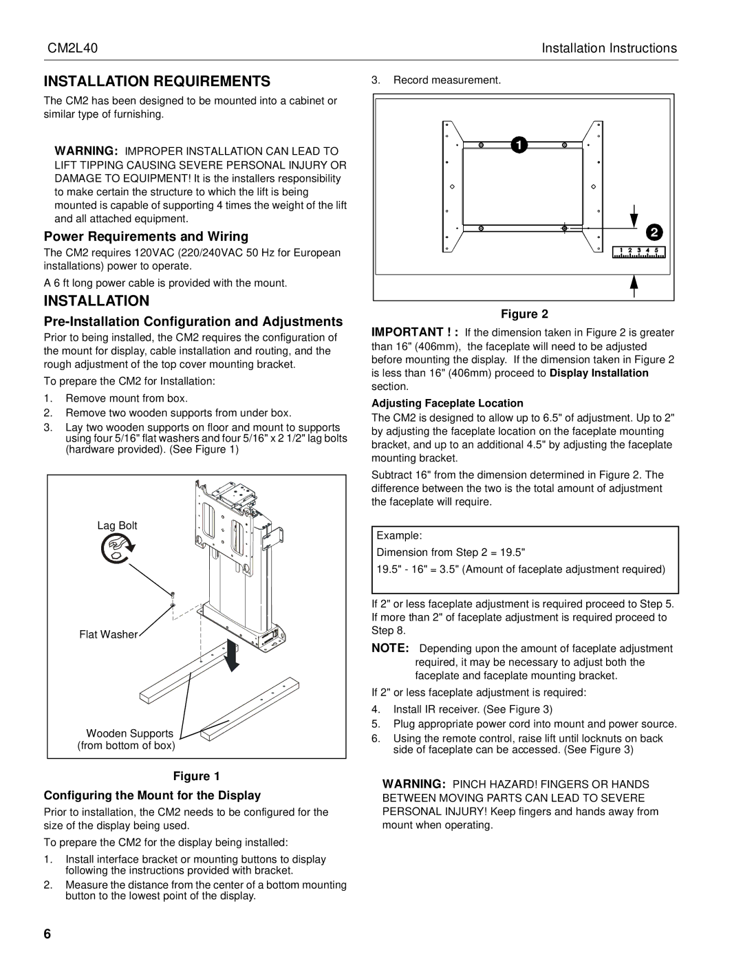
3.Lay two wooden supports on floor and mount to supports using four 5/16" flat washers and four 5/16" x 2 1/2" lag bolts (hardware provided). (See Figure 1)

Lag Bolt

Flat Washer

Wooden Supports

(from bottom of box)

Figure 1

Configuring the Mount for the Display

Prior to installation, the CM2 needs to be configured for the size of the display being used.

To prepare the CM2 for the display being installed:

1.Install interface bracket or mounting buttons to display following the instructions provided with bracket.

2.Measure the distance from the center of a bottom mounting button to the lowest point of the display.

3.Record measurement.

1

2

Figure 2

IMPORTANT ! : If the dimension taken in Figure 2 is greater than 16" (406mm), the faceplate will need to be adjusted before mounting the display. If the dimension taken in Figure 2 is less than 16" (406mm) proceed to Display Installation section.

Adjusting Faceplate Location

The CM2 is designed to allow up to 6.5" of adjustment. Up to 2" by adjusting the faceplate location on the faceplate mounting bracket, and up to an additional 4.5" by adjusting the faceplate mounting bracket.

Subtract 16" from the dimension determined in Figure 2. The difference between the two is the total amount of adjustment the faceplate will require.

Example:

Dimension from Step 2 = 19.5"

19.5" - 16" = 3.5" (Amount of faceplate adjustment required)

If 2" or less faceplate adjustment is required proceed to Step 5. If more than 2" of faceplate adjustment is required proceed to Step 8.

NOTE: Depending upon the amount of faceplate adjustment required, it may be necessary to adjust both the faceplate and faceplate mounting bracket.

If 2" or less faceplate adjustment is required:

4.Install IR receiver. (See Figure 3)

5.Plug appropriate power cord into mount and power source.

6.Using the remote control, raise lift until locknuts on back side of faceplate can be accessed. (See Figure 3)

WARNING: PINCH HAZARD! FINGERS OR HANDS BETWEEN MOVING PARTS CAN LEAD TO SEVERE PERSONAL INJURY! Keep fingers and hands away from mount when operating.

6

Page 6
Image 6
Chief Manufacturing CM2L40 Installation Requirements, Power Requirements and Wiring, Configuring the Mount for the Display

CM2L40 specifications

The Chief Manufacturing CM2L40 is an exemplary product in the realm of LCD and plasma display mounting solutions, designed particularly for commercial and institutional environments. This mount stands out for its robust construction and versatile functionality, catering to a wide range of television sizes and weight capacities.

One of the standout features of the CM2L40 is its exceptional weight capacity, supporting displays up to 400 pounds. This makes it ideal for mounting larger screens that are often required in professional settings such as conference rooms, classrooms, and public venues. The mount’s sturdy design ensures that it can hold heavy displays securely, providing peace of mind for users.

The CM2L40 is engineered with versatility in mind. It offers a variety of mounting options, including fixed, tilting, and full-motion capabilities. This adaptability allows users to position their displays at optimal viewing angles, enhancing the overall viewing experience. The tilting feature is particularly beneficial in environments where viewers might be seated below the screen, as it helps reduce glare and provides a better line of sight.

Installation of the CM2L40 is made simple with its user-friendly design. The mount includes a quick-release mechanism for easy access to the display, enabling effortless adjustments and maintenance. Additionally, the mount is compatible with various VESA patterns, offering flexibility for different screen brands and sizes.

A key technology used in the CM2L40 is its integrated cable management system. This feature helps to organize and conceal wiring, resulting in a cleaner and more professional appearance. By minimizing clutter, the mount contributes to a more aesthetically pleasing setup, which is essential in commercial environments.

Durability is another hallmark of the Chief Manufacturing CM2L40. Constructed from high-quality materials, it is designed to withstand the rigors of daily use in demanding environments. Its powder-coated finish not only enhances its visual appeal but also protects it from scratches and corrosion.

Overall, the Chief Manufacturing CM2L40 is an outstanding choice for anyone in need of a heavy-duty mount solution. Its combination of strength, versatility, and user-friendly features make it a smart investment for commercial applications, ensuring that display technology can be utilized effectively and stylishly. Whether for presentations, lectures, or digital signage, the CM2L40 provides a reliable platform for any large display need.