Installation Instructions | CMA351 | |
7. | Using a pipe wrench, install | |
| ANSI/ASME B1.20.1 (Schedule 40, 0.154" minimum | |
| thickness aluminum - ASTM B221) threaded extension | |
| column (not included) into swivel adapter (A) until tight, with | |
| a minimum of four threads engaged. |
|
8. | Secure lower 1 1/2" NPT pipe to swivel adapter (A) using | |
| (E) | |
WARNING: Exceeding the weight capacity can result in | ||
serious personal injury or damage to equipment! It is the | ||
installer’s responsibility to make sure the combined weight of | ||
all components located between the CMA351 up to (and | ||
including) the display/projector does not exceed 500 lbs | ||
(226.8 kg). |
| |
| The weight capacity of the CMA351 may be LIMITED to | |
| the lowest weight capacity of any other component located | |
| between the CMA351 and the supporting structure! | |
|
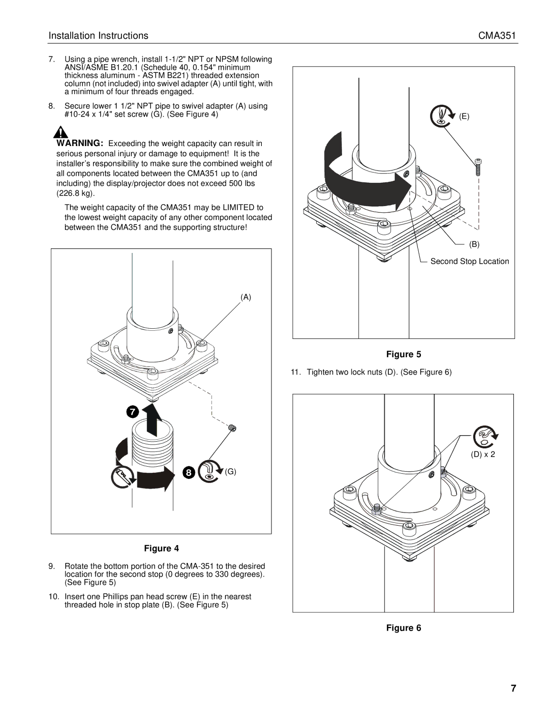
| (B) |
|
| Second Stop Location |
|
| (A) |
|
| Figure 5 |
|
| 11. Tighten two lock nuts (D). (See Figure 6) |
| 7 |
|
|
| (D) x 2 |
| 8 | (G) |
| Figure 4 |
|
9. | Rotate the bottom portion of the | |
| location for the second stop (0 degrees to 330 degrees). | |
| (See Figure 5) |
|
10. | Insert one Phillips pan head screw (E) in the nearest | |
| threaded hole in stop plate (B). (See Figure 5) | |
Figure 6
7