Chief Manufacturing FDP Series Pole-MountingBracket Assembly and Installation

Models: FDP Series

1 2
Download 2 pages 45.54 Kb
Page 2
Image 2
Pole-Mounting Bracket Assembly and Installation:

Pole-Mounting Bracket Assembly and Installation:

1.Assemble two pole-mounting bracket halves as shown in Figure 3 and secure using two ¼-20 X 4.25” hex bolts and two ¼” flat washers.

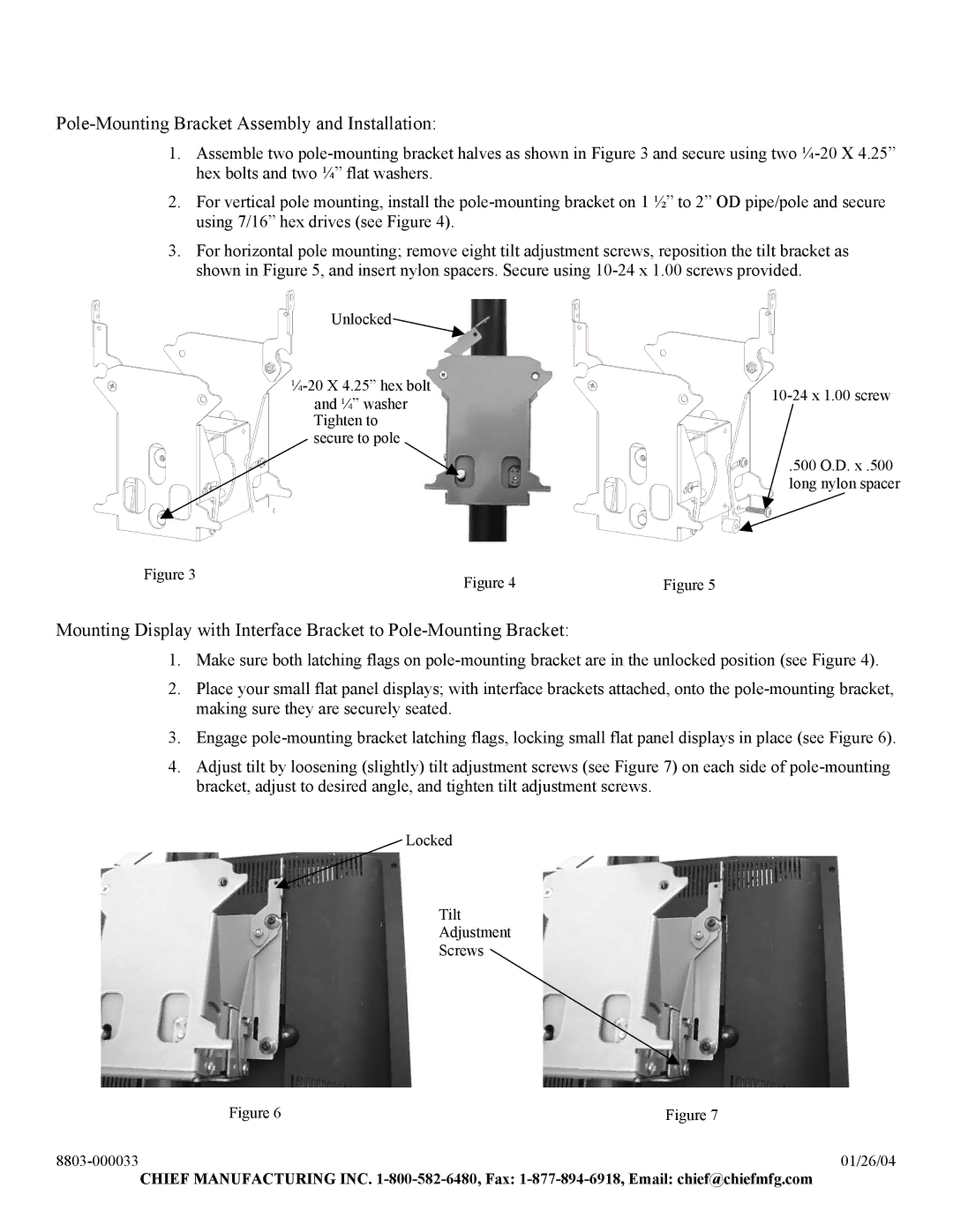
2.For vertical pole mounting, install the pole-mounting bracket on 1 ½” to 2” OD pipe/pole and secure using 7/16” hex drives (see Figure 4).

3.For horizontal pole mounting; remove eight tilt adjustment screws, reposition the tilt bracket as shown in Figure 5, and insert nylon spacers. Secure using 10-24 x 1.00 screws provided.

Unlocked


¼-20 X 4.25” hex bolt

10-24 x 1.00 screw

and ¼” washer


Tighten to


secure to pole


.500 O.D. x .500


long nylon spacer

Figure 3

Figure 4

Figure 5


Mounting Display with Interface Bracket to Pole-Mounting Bracket:

1.Make sure both latching flags on pole-mounting bracket are in the unlocked position (see Figure 4).

2.Place your small flat panel displays; with interface brackets attached, onto the pole-mounting bracket, making sure they are securely seated.

3.Engage pole-mounting bracket latching flags, locking small flat panel displays in place (see Figure 6).

4.Adjust tilt by loosening (slightly) tilt adjustment screws (see Figure 7) on each side of pole-mounting bracket, adjust to desired angle, and tighten tilt adjustment screws.

Locked

Tilt

Adjustment

Screws

Figure 6

Figure 7

8803-000033

01/26/04

CHIEF MANUFACTURING INC. 1-800-582-6480, Fax: 1-877-894-6918, Email: chief@chiefmfg.com

Page 2
Image 2
Chief Manufacturing FDP Series installation instructions Pole-MountingBracket Assembly and Installation