
FWDIW-I Series specifications
The Chief Manufacturing FWDIW-I Series is a remarkable line of wall mounts designed specifically for flat panel displays, establishing a new standard in the industry. Tailored to meet the diverse needs of commercial and residential settings, this series combines both functionality and aesthetics.One of the standout features of the FWDIW-I Series is its exceptional versatility. Designed to accommodate a wide range of display sizes, the mounts support screens from 42 inches up to 80 inches, making them ideal for various environments, including corporate offices, schools, and homes. This adaptability ensures that the FWDIW-I Series can be utilized in numerous applications, from boardrooms to home theaters.
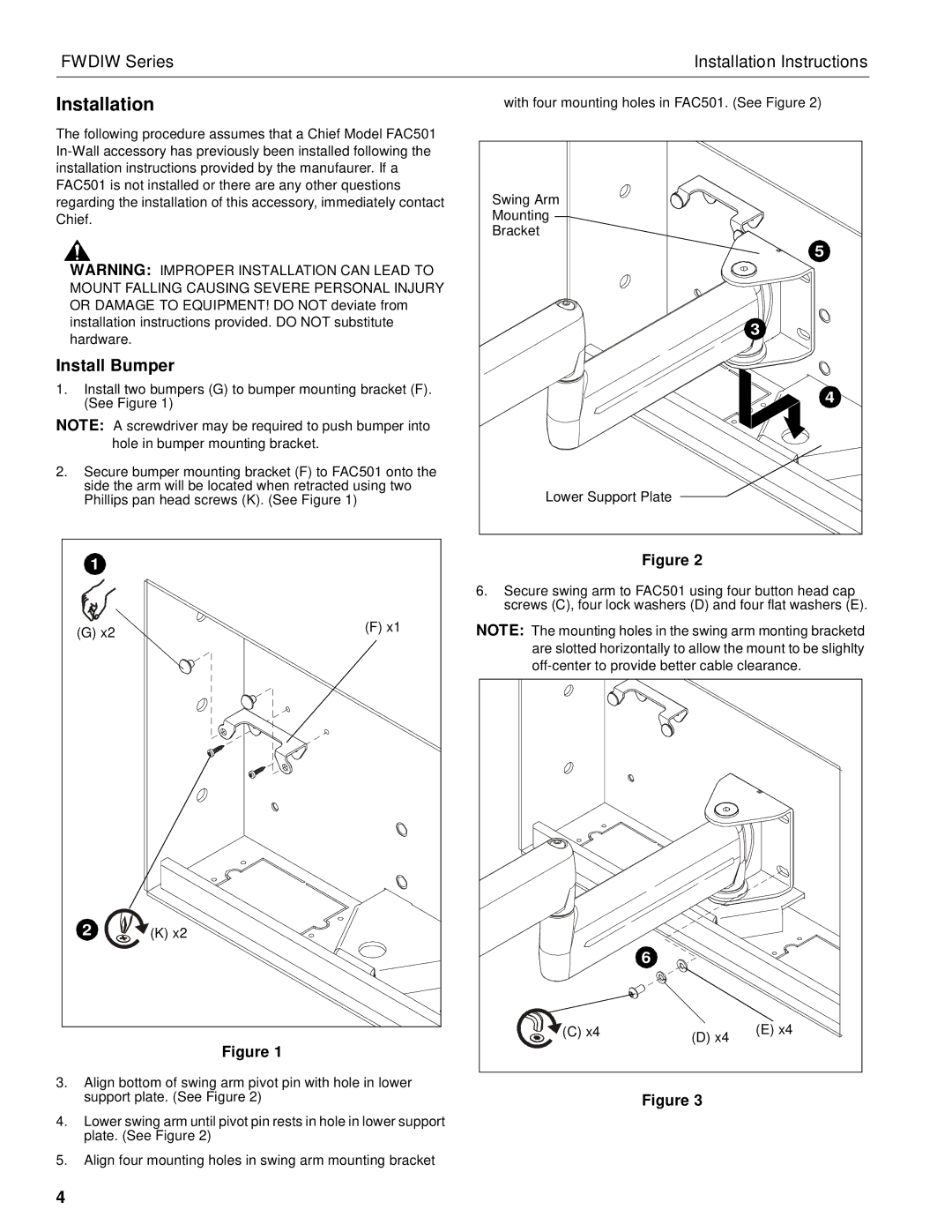
The installation process is streamlined and user-friendly, which is a significant advantage for both professionals and DIY enthusiasts. With the innovative ClickConnect™ technology, users can easily attach and detach the display without the need for additional tools. This feature not only simplifies the mounting process but also ensures that adjustments can be made with minimal effort. Additionally, the mounts come with a built-in leveling feature that allows for precise adjustments after installation.
The FWDIW-I Series incorporates robust materials and advanced engineering technologies to ensure durability and stability. The mounts are constructed with heavy-duty steel, providing a strong foundation for even the largest screens. This reliability is especially important in public installations where safety and security are paramount.
Another notable characteristic of the series is the cable management system that is integrated into the design. This system helps to keep wires and cables organized and out of sight, contributing to a clean and professional appearance. The sleek design of the mounts complements modern décor and enhances the overall aesthetic of the space.
Moreover, the FWDIW-I Series supports a full range of motion. With features such as tilt, swivel, and portrait/landscape orientations, users can enjoy flexibility in their display positioning. This adaptability caters to various viewing angles, ensuring optimal visibility for everyone in the room.
To summarize, the Chief Manufacturing FWDIW-I Series is an outstanding choice for those seeking high-quality wall mounts for flat panel displays. With its versatile compatibility, user-friendly installation, durable construction, and added features like cable management, this series stands out in a competitive market. Whether for commercial or residential use, the FWDIW-I Series is designed to meet the demands of modern display applications.