Installation Instructions |
|
| LCD2TS | |
Assembly And Installation |
|
|
| |
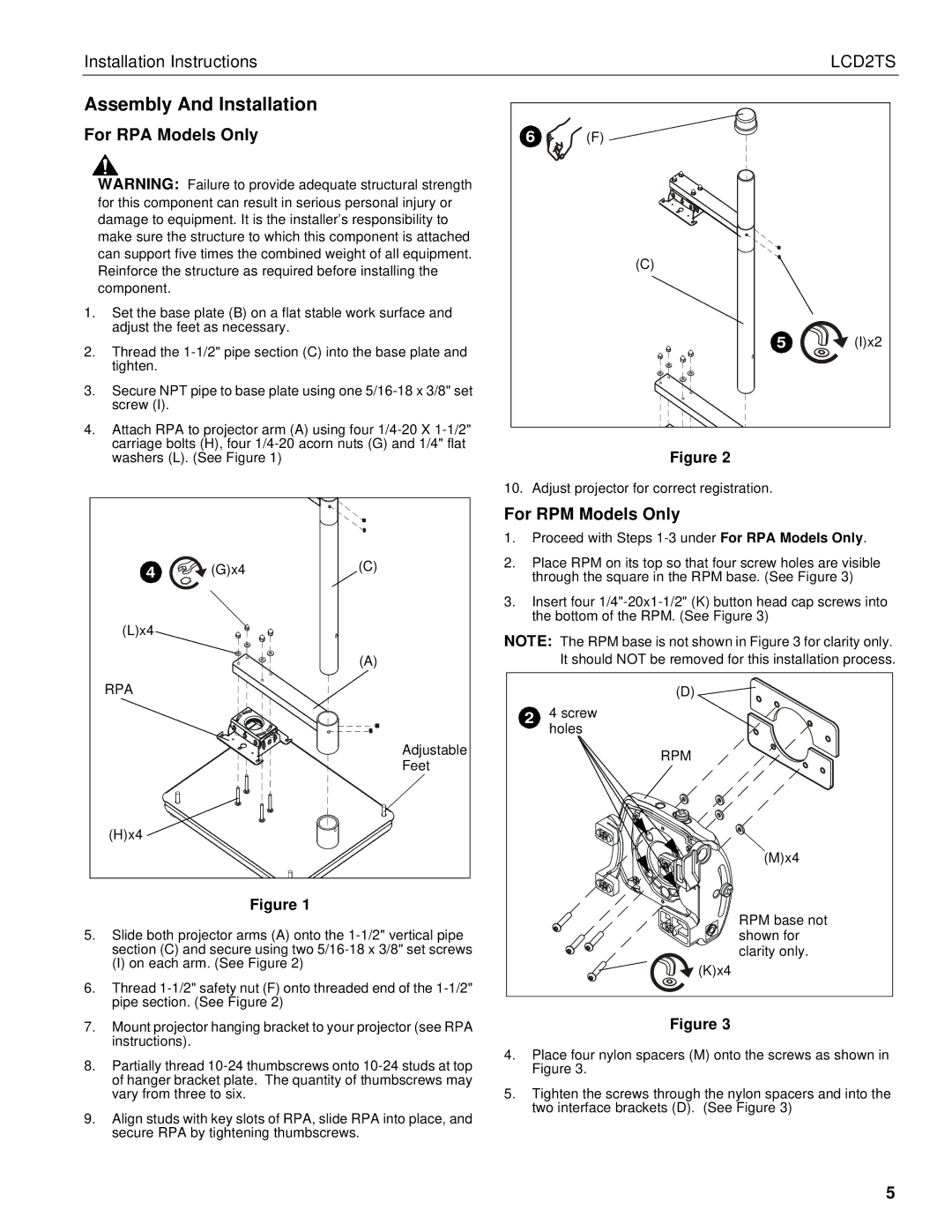
For RPA Models Only | 6 | (F) |
| |
| WARNING: Failure to provide adequate structural strength |
|
|
|
| for this component can result in serious personal injury or |
|
|
|
| damage to equipment. It is the installer’s responsibility to |
|
|
|
| make sure the structure to which this component is attached |
|
|
|
| can support five times the combined weight of all equipment. |
| (C) |
|
| Reinforce the structure as required before installing the |
|
| |
|
|
|
| |
| component. |
|
|
|
1. Set the base plate (B) on a flat stable work surface and |
|
|
| |
| adjust the feet as necessary. |
| 5 | (I)x2 |
2. Thread the |
| |||
|
|
| ||
| tighten. |
|
|
|
3. | Secure NPT pipe to base plate using one |
|
|
|
| screw (I). |
|
|
|
4. Attach RPA to projector arm (A) using four |
|
|
| |
| carriage bolts (H), four |
| Figure 2 |
|
| washers (L). (See Figure 1) |
|
| |
|
| 10. Adjust projector for correct registration. |
| |
4 | (G)x4 | (C) |
(L)x4 |
|
|
|
| (A) |
RPA |
|
|
|
| Adjustable |
|
| Feet |
(H)x4 |
|
|
Figure 1
5.Slide both projector arms (A) onto the
(I) on each arm. (See Figure 2)
6.Thread
For RPM Models Only
1.Proceed with Steps 1-3 under For RPA Models Only.
2.Place RPM on its top so that four screw holes are visible through the square in the RPM base. (See Figure 3)
3.Insert four
NOTE: The RPM base is not shown in Figure 3 for clarity only. It should NOT be removed for this installation process.
| (D) |
2 | 4 screw |
| holes |
| RPM |
| (M)x4 |
| RPM base not |
| shown for |
| clarity only. |
| (K)x4 |
7.Mount projector hanging bracket to your projector (see RPA instructions).
8.Partially thread
9.Align studs with key slots of RPA, slide RPA into place, and secure RPA by tightening thumbscrews.
Figure 3
4.Place four nylon spacers (M) onto the screws as shown in Figure 3.
5.Tighten the screws through the nylon spacers and into the two interface brackets (D). (See Figure 3)
5