Installation Instructions | PCM SERIES |
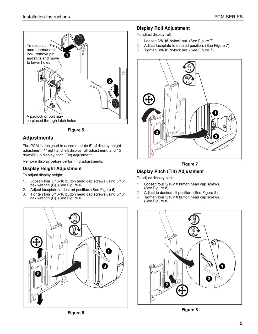
To use as a ![]()
![]()
![]()
![]() more permanent
more permanent ![]()
![]() lock, remove pin and nuts and move to lower holes
lock, remove pin and nuts and move to lower holes ![]()
1
2
Display Roll Adjustment
To adjust display roll:
1.Loosen
2.Adjust faceplate to desired position. (See Figure 7)
3.Tighten
1 |
A padlock or bolt may
be placed through latch holes
Figure 5
Adjustments
The PCM is designed to accommodate 5" of display height adjustment, 4º right and left display roll adjustment, and 15º down/5º up display pitch (Tilt) adjustment.
Remove display before performing adjustments.
Display Height Adjustment
To adjust display height:
1.Loosen four
2.Adjust faceplate to desired position. (See Figure 6)
3.Tighten four
1 |
3 |
2 |
Figure 6
2 |
3 |
Figure 7
Display Pitch (Tilt) Adjustment
To adjust display pitch:
1.Loosen four
2.Adjust to desired tilt position. (See Figure 8)
3.Tighten four
1 |
3 |
2 |
Figure 8
5