103-002001 specifications
Christie Digital Systems 103-002001 is a robust and versatile solution designed to push the boundaries of visual display technology. Renowned for its reliability and performance, this product is ideal for diverse applications, ranging from corporate environments to cinematic experiences and entertainment venues.One of the standout features of the Christie 103-002001 is its impeccable imaging capabilities. It supports a high native resolution that ensures crystal-clear visuals, making it suitable for applications where image quality is paramount. The device is engineered for high brightness, ensuring optimal visibility even in well-lit environments. This makes it an excellent choice for large venues like auditoriums, trade shows, and stadiums where ambient light cannot be controlled.
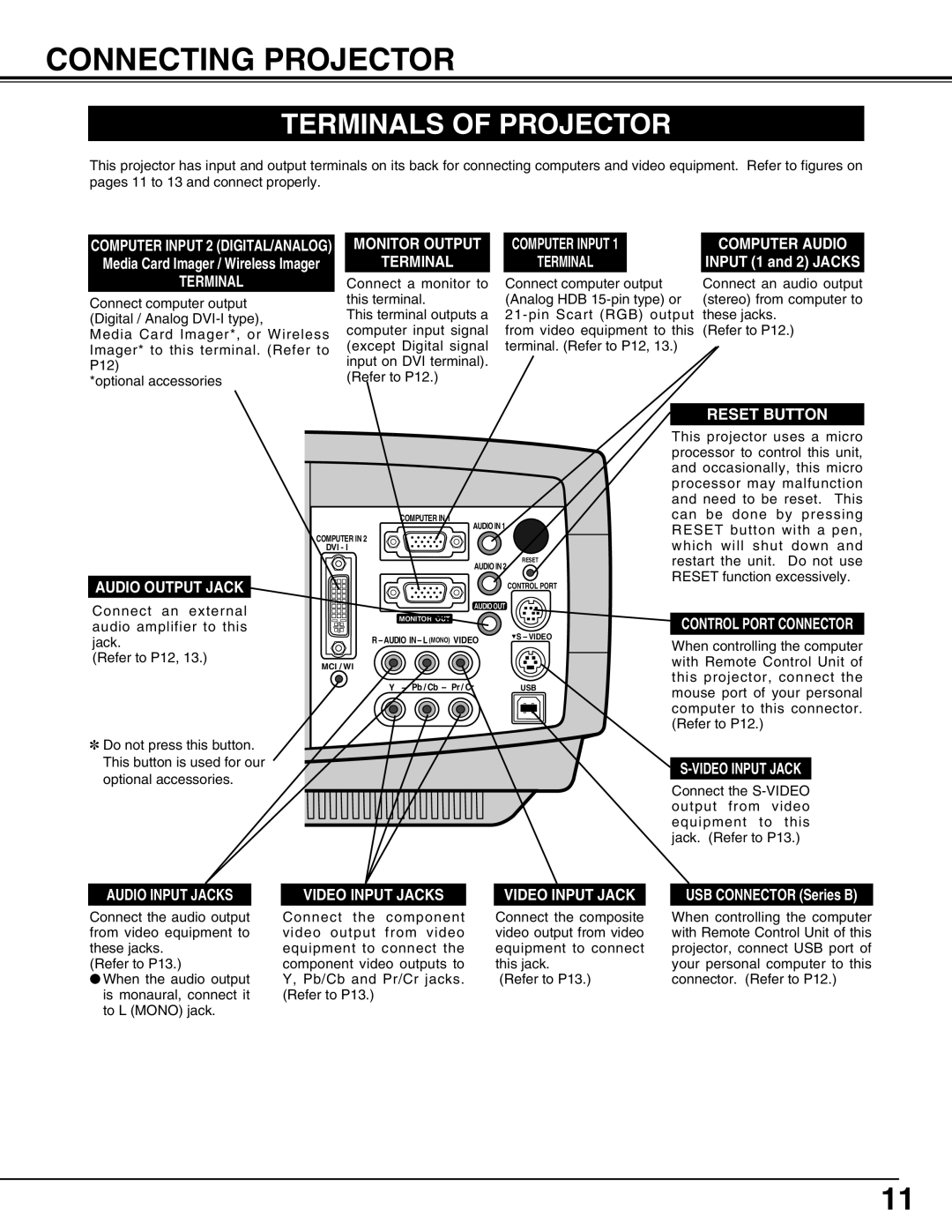
In terms of connectivity, the Christie 103-002001 boasts a variety of input options. It supports both digital and analog interfaces, accommodating a wide range of devices such as computers, video players, and streaming equipment. This versatility allows for seamless integration into existing setups, making it a flexible solution for businesses and event organizers.
The technology behind the Christie 103-002001 includes advanced projection methods that enhance color accuracy and uniformity. The use of cutting-edge optics ensures that images are not just bright but also rich in color depth, providing viewers with an immersive experience. The device is also equipped with intelligent processing technologies that optimize image scaling and aspect ratios, delivering a flawless presentation regardless of source material.
Durability is another key characteristic of the Christie 103-002001. Built with high-quality materials, it is designed for longevity and to withstand the rigors of frequent use. The device features efficient cooling systems that maintain optimal operating temperatures, ensuring consistent performance during extended periods of use, which is critical in environments like theaters and conference halls.
Additionally, the Christie 103-002001 incorporates user-friendly features, including intuitive controls and comprehensive remote management options. This simplifies operation and allows users to adjust settings quickly and easily, enhancing overall productivity.
In summary, the Christie Digital Systems 103-002001 is a powerhouse of visual technology that combines high resolution, versatile connectivity, and advanced imaging capabilities. Its durability and ease of use make it an invaluable asset for anyone looking to deliver exceptional visual experiences in professional environments.