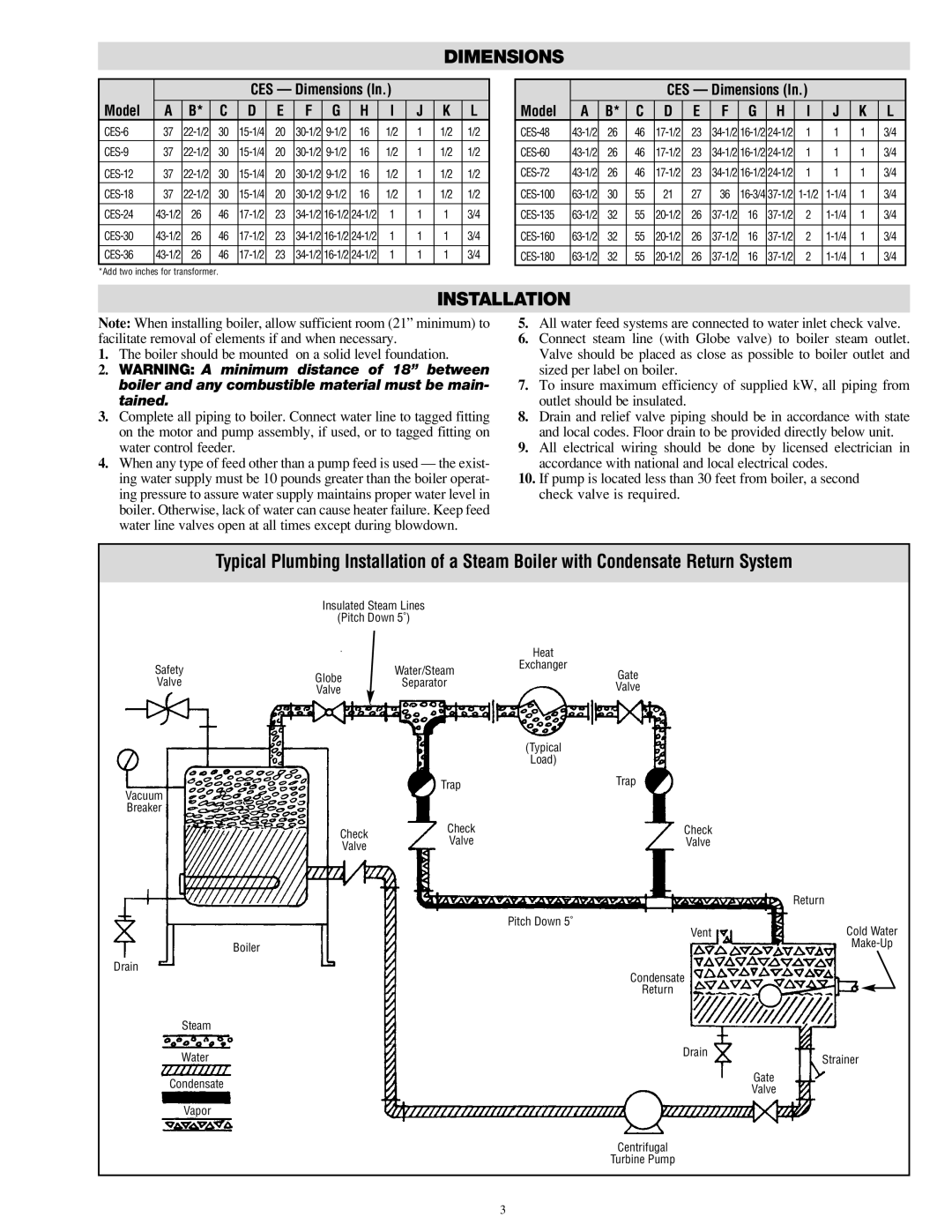
CES-6 specifications
The Chromalox CES-6 is a state-of-the-art electric heating solution designed for industrial and commercial applications. This versatile unit offers a range of features that enhance its efficiency, durability, and ease of use. With a focus on advanced technology, the CES-6 is engineered to meet the demands of various heating requirements, from process heating to temperature maintenance.One of the standout features of the CES-6 is its robust construction. Built to withstand harsh environments, it is made from high-quality materials that ensure longevity and reliability. The unit's enclosure is resistant to moisture and dust, making it ideal for applications in challenging conditions. This durability ensures that the CES-6 can operate effectively in settings such as manufacturing plants, warehouses, and outdoor installations.
The CES-6 leverages cutting-edge heating technologies, including advanced thermal management systems. This feature allows for precise temperature control, ensuring optimal performance and energy efficiency. By utilizing programmable temperature settings, users can customize their heating profiles to match specific operational needs, reducing energy consumption and operating costs.
Another significant characteristic of the CES-6 is its ease of installation and maintenance. Designed with user convenience in mind, the unit comes equipped with adaptable mounting options and user-friendly interfaces. This makes it straightforward for technicians to install and service, minimizing downtime and enhancing productivity.
Safety is a top priority with the CES-6, which incorporates multiple safety features to protect users and equipment. Over-temperature protection, built-in alarm systems, and fail-safe mechanisms are just a few of the safeguards included. These features not only enhance user safety but also contribute to the overall integrity of the heating process.
In conclusion, the Chromalox CES-6 stands out in the market for its combination of durability, advanced technology, and user-friendly design. Its robust construction makes it suitable for demanding industrial settings, while its energy-efficient heating capabilities and ease of installation ensure it meets the needs of a wide range of applications. Whether you are looking for reliable heating for your manufacturing processes or need a dependable solution for temperature maintenance, the CES-6 is an exceptional choice that delivers performance and efficiency.

