WIRING
ELECTRIC SHOCK HAZARD. Disconnect all power before installing or servicing heater. Failure to do so could result in personal injury or property damage. Heater must be installed by a qualified person in accor- dance with the National Electrical Code, NFPA 70.
ELECTRIC SHOCK HAZARD. Any installation involving electric heaters must be performed by a qualified per- son and must be effectively grounded in accordance with the National Electrical Code to eliminate shock hazard.
1.Be sure line voltage matches heater voltage (on nameplate).
2.Electric wiring to heater must be installed in accordance with the National Electrical Code and local codes by a qualified person as defined in the NEC.
3.Remove terminal cover by backing out screw in center of cover and feed wires through BX mounting bracket. (See Table B for rec- ommended wire size.)
4.Connect one wire to the unused heater terminal and one to the unused thermostat terminal.
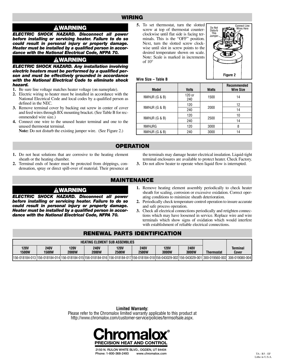
Note: Do not disturb the existing jumper wire. (See Figure 2.)
5.To set thermostat, turn the slotted ![]()
screw at top of thermostat counter- clockwise until flat side is facing ter- minals. This is the “OFF” position. Next, turn the slotted screw clock- wise until slot in screw points to the desired temperature shown on scale. Note: Scale is marked in increments of 10°
Wire Size – Table B |
|
|
| Figure 2 |
|
|
|
| |
|
|
|
| |
|
|
|
|
|
|
|
|
| Recommended |
Model | Volts |
| Watts | Wire Size |
NWHJR (G & B) | 120 or |
| 1500 | 14 |
240 |
| |||
|
|
|
| |
NWHJR (G & B) | 120 |
| 2000 | 12 |
240 |
| 14 | ||
|
|
| ||
NWHJR (G & B) | 120 |
| 2500 | 10 |
240 |
| 14 | ||
|
|
| ||
NWHJRG | 120 |
| 3000 | 8 |
NWHJR (G & B) | 240 |
| 3000 | 14 |
OPERATION
1.Do not heat solutions that are corrosive to the heating element sheath or the heating chamber.
2.Terminal ends of heater must be protected from drippings, con- densation, spray or direct
the terminals may damage heater electrical insulation.
3.Do not allow heater to operate when liquid flow is interrupted.
MAINTENANCE
ELECTRIC SHOCK HAZARD. Disconnect all power before installing or servicing heater. Failure to do so could result in personal injury or property damage. Heater must be installed by a qualified person in accor- dance with the National Electrical Code, NFPA 70.
1.Remove heating element assembly periodically to check heater sheath for scaling, corrosion or excessive oxidation. Correct oper- ating conditions to minimize sheath deterioration.
2.Periodically check temperature control operation to insure accurate and safe process operation.
3.Check all electrical connections periodically and retighten connec- tions which may have loosened in service. Replace wire and wire terminals which show signs of oxidation which would interfere with establishment of reliable electrical connections.
RENEWAL PARTS IDENTIFICATION
|
|
| HEATING ELEMENT SUB ASSEMBLIES |
|
|
|
|
| |||
120V | 240V | 120V |
| 240V | 120V |
| 240V | 120V | 240V |
| Terminal |
1500W | 1500W | 2000W |
| 2000W | 2500W |
| 2500W | 3000W | 3000W | Thermostat | Cover |
|
|
|
|
|
|
|
|
|
|
|
|
Limited Warranty:
Please refer to the Chromalox limited warranty applicable to this product at
2150 N. RULON WHITE BLVD., OGDEN, UT 84404 |
| |
Phone: | www.chromalox.com | TA - R5 - EF |
Litho in U.S.A.