in CHAPTER 11, they indicate the load will be below 3 ohms (except for the 51 models). Because this occurs only over a small range of frequencies and because of the nature of audio signals, a 4 Ohm amplifier should be able to drive this load with no problems. However, for models that have a nominal 2 Ohm impedance when paralleled, use caution by ensuring that your amplifier is both rated for 2 Ohms and has adequate cooling.
PARALLELED | PASSIVE MODE | BIAMP MODE | BIAMP MODE |
MODELS | IMPEDANCE | LF IMPEDANCE | HF IMPEDANCE |
2 x 41 | 4 Ohms | 4 Ohms | 4 Ohms |
2 x 42 | 4 Ohms | 4 Ohms | 4 Ohms |
2 x 43 | 4 Ohms | 4 Ohms | 4 Ohms |
2 x 46 | 2 Ohms | 2 Ohms | 4 Ohms |
2 x 47 | 2 Ohms | 2 Ohms | 4 Ohms |
2 x 48 | 4 Ohms | 4 Ohms | 4 Ohms |
2 x 51 | 4 Ohms | N/A | N/A |
2 x 55 | 2 Ohms | N/A | N/A |
Table 7: Nominal Impedances for Two XLT or XLTE Loudspeakers In Parallel
6.4CONNECTING THE LOUDSPEAKERS
The following diagrams show the wiring connections for the loudspeakers. Be sure to observe proper polarity when making the connections. This means making sure the positive (+) on the amplifier connects to the positive (+) on the loudspeaker and negative
POLARITY CHECK FOR TWO LOUDSPEAKERS OR SUBWOOFERS:
A simple check for proper polarity is to stand in front of and exactly between two loudspeakers or subwoofers. Play a mono source through the system. If the sound does not appear to come solidly from a point between the loudspeakers and/or the bass is weak, they are probably out of polarity. Check the + and - wiring for the entire signal chain to each loudspeaker. The wiring should be identical.
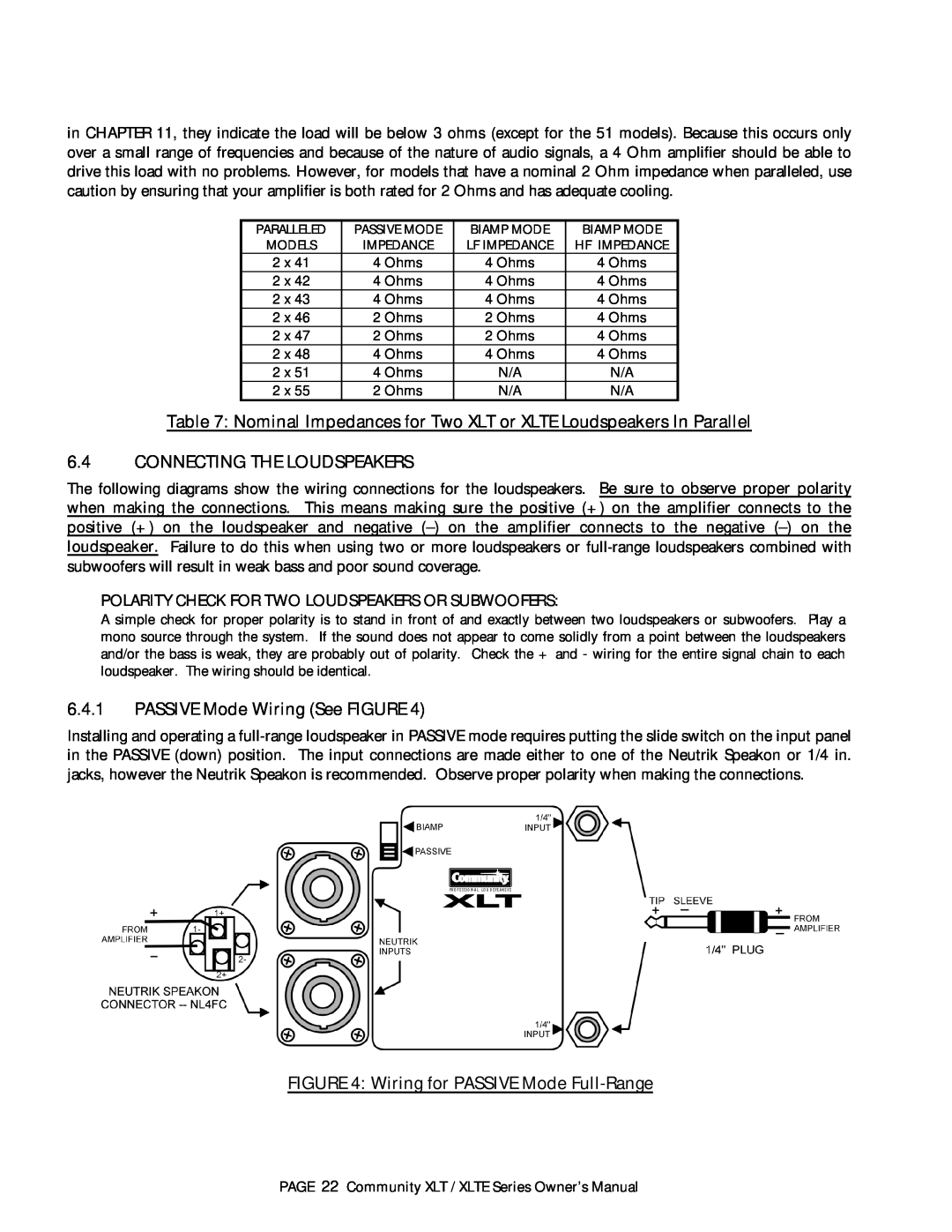
6.4.1PASSIVE Mode Wiring (See FIGURE 4)
Installing and operating a
FIGURE 4: Wiring for PASSIVE Mode Full-Range
PAGE 22 Community XLT / XLTE Series Owner’s Manual
