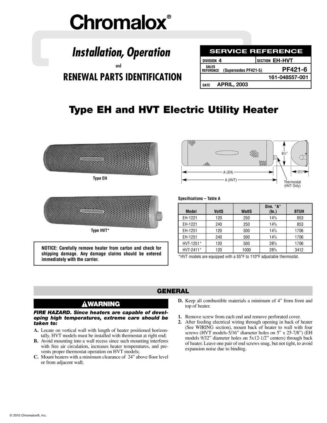
PF421-6 specifications
The Chromalox PF421-6 is an innovative electric heater designed for industrial and commercial applications, renowned for its efficiency, durability, and versatility. This heater is engineered to provide consistent and reliable performance in various settings, including process heating, space heating, and equipment protection. Its robust construction and advanced features make it a preferred choice for professionals seeking a reliable heating solution.One of the standout features of the PF421-6 is its advanced control system, which allows for precise temperature management. This control system can be easily integrated into existing processes, ensuring optimal heating performance tailored to specific requirements. The heater supports a variety of control options, including on/off, proportional control, and multi-zone temperature management. This versatility ensures that users can adapt the heating performance to suit their operational needs.
The Chromalox PF421-6 also incorporates advanced heating technologies, including high-efficiency heating elements that provide rapid heat-up times while minimizing energy consumption. The heater's design promotes uniform heat distribution, preventing hot spots and ensuring even heating across surfaces. This characteristic is particularly beneficial in applications where temperature consistency is crucial.
Constructed from high-quality materials, the PF421-6 is built to withstand harsh operating environments. Its robust housing and high-grade insulation contribute to its longevity and reliability, even under heavy use. Additionally, the heater's compact design makes it easy to install and integrate into existing systems without requiring extensive modifications.
Safety is a paramount consideration in the design of the PF421-6. The heater is equipped with multiple safety features, including over-temperature protection and fault detection systems. These mechanisms help prevent accidents and ensure safe operation, making it suitable for a range of industries, from food processing to chemical manufacturing.
Finally, the Chromalox PF421-6 is also notable for its low maintenance requirements. With minimal moving parts and its durable construction, users can expect reduced downtime and lower operational costs. This reliability, combined with its advanced features and technologies, makes the PF421-6 a trusted heating solution for professionals seeking long-term performance and efficiency in their operations.