MAINTENANCE
WARNING: Hazard of Shock. Disconnect all power to heater before servicing or replacing heaters. Do not attempt to service heater while unit is operat- ing as there is hazard of electric shock, injury from operating fan, and burns from hot heating elements.
1.Before activating for next heating season, vacuum or use com- pressed air to remove accumulated dust or lint, which other- wise may restrict proper air flow.
2.Periodically check all electrical connections and retighten to avoid electrical wiring difficulties.
|
|
|
|
|
|
|
|
|
|
|
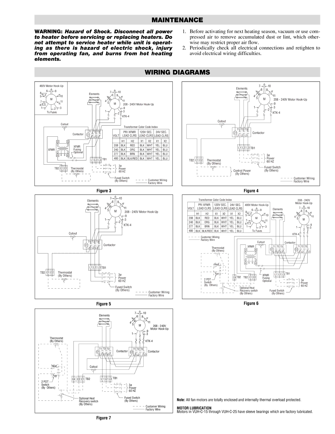
| WIRING DIAGRAMS |
|
|
|
|
| |||||
480V Motor |
|
|
|
|
|
|
|
|
|
|
|
|
|
| Elements | 7 |
| 10 | ||||
6 | 9 |
|
|
|
|
| 7 | 10 |
|
|
|
|
|
|
|
| 6 |
| 8 | |||
|
|
|
|
|
|
|
|
|
|
|
|
|
|
|
|
| ||||||
8 |
|
|
| Elements |
|
|
|
|
|
|
|
|
|
|
|
|
|
| ||||
| 10 |
| 6 | 8 |
|
|
|
|
|
|
|
|
|
|
| 4 5 |
| 11 | ||||
5 |
|
|
|
|
|
|
|
|
|
|
|
|
|
| ||||||||
|
|
|
|
|
|
|
|
|
|
|
|
|
|
|
|
| ||||||
M |
|
|
|
|
|
|
|
|
|
|
|
|
|
|
|
|
| M | ||||
7 | 11 |
|
|
| 4 5 |
|
| 11 |
|
|
|
|
|
|
|
|
|
|
| 208 - 240V Motor | ||
|
|
|
|
| M |
|
|
|
|
|
|
|
|
|
|
|
| 9 | ||||
|
|
|
|
| 208 - 240V Motor |
|
|
|
|
|
|
|
|
| ||||||||
4 |
|
|
|
|
|
|
|
|
|
|
|
|
|
| 1 |
| ||||||
1 | 2 | 3 |
|
|
|
|
|
| 9 |
|
|
|
|
|
|
|
|
|
|
| 3 | |
|
|
|
|
| 1 |
|
| 3 |
|
|
|
|
|
|
|
|
|
|
|
| 2 | |
To Fuses |
|
|
|
|
| 2 |
|
|
|
|
|
|
|
|
|
|
|
|
| |||
|
|
|
|
|
|
|
|
|
|
|
|
|
|
|
|
| ||||||
|
|
|
|
|
|
|
|
|
|
|
|
|
|
|
|
|
|
|
|
| ||
|
| Cutout |
|
|
|
|
|
|
|
|
|
|
|
|
|
| Cutout |
|
|
|
|
|
|
|
|
|
|
|
|
| Transformer Color Code Index |
|
|
|
|
|
|
|
|
| |||||
|
|
|
|
|
|
|
|
|
|
|
| T1 T2 | T3 |
|
|
| ||||||
|
|
|
| T1 | T2 | T3 |
|
| PRI XFMR | 120V SEC. | 24V SEC. |
|
| Contactor |
| |||||||
|
|
| Contactor |
|
|
|
| C1 |
|
|
| |||||||||||
|
|
| C1 |
|
|
|
|
|
|
|
|
| ||||||||||
|
|
| L2 L3 |
| VOLT | LEAD CLRS | LEAD CLRS LEAD CLRS |
|
| L1 L2 L3 |
|
|
| |||||||||
|
|
|
| L1 |
|
|
|
|
|
| ||||||||||||
|
|
|
|
|
|
|
|
|
|
|
|
|
|
|
|
|
|
|
| |||
| X1 | X2 |
|
|
|
|
|
| H1 | H2 | X1 | X2 | X1 | X2 |
|
|
|
|
|
|
|
|
|
|
| XFMR |
|
|
|
| 208 | BLK | RED | BLK | WHT | YEL | BLU |
|
| L1 L2 | L3 TB1 |
|
| ||
| XFMR |
| Fusing |
|
|
|
| 240 | BLK | ORG | BLK | WHT | YEL | BLU |
|
|
|
| ||||
|
|
| Optional |
|
|
|
| 277 | BLK | BRN | BLK | WHT | YEL | BLU |
|
|
|
|
|
|
| 3ø |
| H1 | H2 |
|
|
|
|
|
|
|
|
|
|
|
| ||||||||
|
|
|
|
|
|
|
|
|
|
|
|
|
|
|
|
|
|
|
| |||
|
|
|
| L1 L2 | L3 TB1 |
| 480 | BLK | BLK/RED | BLK | WHT | YEL | BLU | TB2 | C1 C2 | Thermostat |
|
|
|
| Power | |
|
|
|
|
|
|
|
|
|
|
|
|
|
|
|
| 60 HZ | ||||||
|
|
|
|
|
|
|
|
|
|
|
|
|
|
|
|
| (By Others) |
|
|
|
| |
|
|
|
|
|
|
|
| 3ø |
|
|
|
|
|
|
|
|
|
|
|
| ||
| TB2 | C1 C2 | Thermostat |
|
|
|
|
|
|
|
|
|
|
|
|
|
|
| Fused Switch | |||
|
|
|
|
| Power |
|
|
|
|
|
|
|
|
|
|
| ||||||
|
|
|
|
|
|
|
|
|
|
|
| Control Power |
| (By Others) | ||||||||
|
|
| (By Others) |
|
|
|
| 60 HZ |
|
|
|
|
|
|
|
| ||||||
|
|
|
|
|
|
|
|
|
|
|
|
|
|
|
|
| (By Others) |
|
|
| ||
|
|
|
|
|
|
|
| Fused Switch |
| Customer Wiring |
|
|
|
|
|
|
| Customer Wiring | ||||
|
|
|
|
|
|
|
| (By Others) |
|
|
|
|
|
|
|
| Factory Wire | |||||
|
|
|
|
|
|
|
|
|
|
|
| Factory Wire |
|
|
|
|
|
|
|
|
| |
Figure 3
Elements |
| 7 | 10 |
| 6 | 8 | |
|
| ||
4 | 5 | M | 11 |
|
| 208 - 240V Motor | |
1 |
|
| 9 |
|
| 3 | |
|
|
| 2 |
|
|
|
Cutout
Figure 4
| Transformer Color Code Index |
|
|
|
|
|
| 208 - 240V | |||||
| PRI XFMR | 120V SEC. | 24V SEC. 480V Motor |
| Motor | ||||||||
|
| 7 | 10 | ||||||||||
VOLT | LEAD CLRS | LEAD CLRS LEAD CLRS |
| 6 | 9 |
| Elements | ||||||
|
|
|
|
|
|
| 8 |
| 6 | 8 | |||
| H1 | H2 | X1 | X2 | X1 | X2 |
|
|
|
| |||
| 5 |
|
| 10 |
| 4 5 | 11 | ||||||
208 | BLK | RED | BLK | WHT | YEL | BLU |
| M |
| ||||
|
|
|
| ||||||||||
240 | BLK | ORG | BLK | WHT | YEL | BLU | 7 |
|
| 11 |
|
| M |
4 |
|
|
|
|
| 9 | |||||||
277 | BLK |
| BLK | WHT | YEL |
|
|
|
|
|
| ||
BRN | BLU 1 |
| 2 | 3 |
| 1 | |||||||
|
| 3 | |||||||||||
480 | BLK | BLK/RED | BLK | WHT | YEL | BLU |
| To Fuses |
|
|
| 2 | |
|
|
|
| ||||||||||
|
| Customer Wiring |
|
|
|
|
|
|
|
|
| ||
|
|
|
|
|
|
|
|
|
|
|
| ||
|
| Factory Wire |
|
|
|
|
|
|
|
|
|
| |
TB2
C1 C2
Thermostat (By Others)
T1 | T2 | T3 | |
C1 | L2 L3 | Contactor | |
L1 |
| ||
L1 L2 | L3 TB1 | ||
3ø Power 60 HZ
 Fused Switch
(By Others)
|
| Cutout |
|
|
| Contactor |
| |
Thermostat | XFMR |
| T1 | T2 T3 | T1 T2 T3 |
| ||
X1 | X2 |
| C1 |
|
| C3 |
| |
(By Others) |
|
|
| L3 | ||||
|
|
| L1 L2 | L3 | L1 L2 | |||
|
|
|
| |||||
Heat | H1 | H2 |
|
|
|
|
|
|
|
|
|
|
|
|
|
| |
Fan | C4 TB2 TB2 | C1 C2 | XFMR | L1 L2 L3 TB1 |
| |||
2 PDT | Fusing |
|
| 3ø |
| |||
|
| Optional |
|
|
| |||
Switch |
|
|
|
|
|
| Power | |
(By Others) | Optional Heat |
|
|
|
| 60 HZ |
| |
|
| Fused Switch |
|
| ||||
| Recovery switch |
|
|
| ||||
Customer Wiring Factory Wire
(By Others) | (By Others) |
Figure 5
|
|
| Elements |
| 7 |
| 10 | ||
|
|
|
| 6 |
| 8 | |||
|
|
|
|
|
|
|
| ||
|
|
|
|
|
|
| 4 5 | M | 11 |
|
|
|
|
|
|
|
| 208 - 240V | |
|
|
|
|
|
|
|
|
| Motor |
|
|
|
|
|
|
| 1 |
| 9 |
|
|
|
|
|
|
| 2 | 3 | |
| Thermostat |
|
|
|
|
|
|
| |
|
|
|
|
|
|
|
| ||
| (By Others) |
|
|
|
|
|
|
| |
|
|
| T1 | T2 T3 | Contactor | T1 T2 T3 | |||
|
| C1 |
|
| C3 |
| Contactor | ||
|
|
| L1 L2 | L3 |
| L1 L2 | L3 | ||
| Heat | Cutout |
|
|
|
|
|
|
|
| Fan | C2 C1 TB2 | L1 L2 L3 TB1 |
|
|
| |||
| C4 |
|
|
| |||||
2 PDT |
|
|
|
|
|
|
|
| |
Switch |
|
|
|
|
| 3ø |
|
| |
(By | Others) |
|
|
|
|
| Power |
|
|
|
|
|
|
|
|
| 60 HZ |
|
|
|
| Optional Heat |
|
|
| Fused Switch |
| ||
|
| Recovery switch |
|
|
| (By Others) |
|
| |
|
| (By Others) |
|
|
|
|
|
| Customer Wiring |
|
|
|
|
|
|
|
|
| |
|
|
|
|
|
|
|
|
| Factory Wire |
Figure 6
Note: All fan motors are totally enclosed and internally thermal overload protected.
MOTOR LUBRICATION
Motors in
Figure 7