MOUNTING

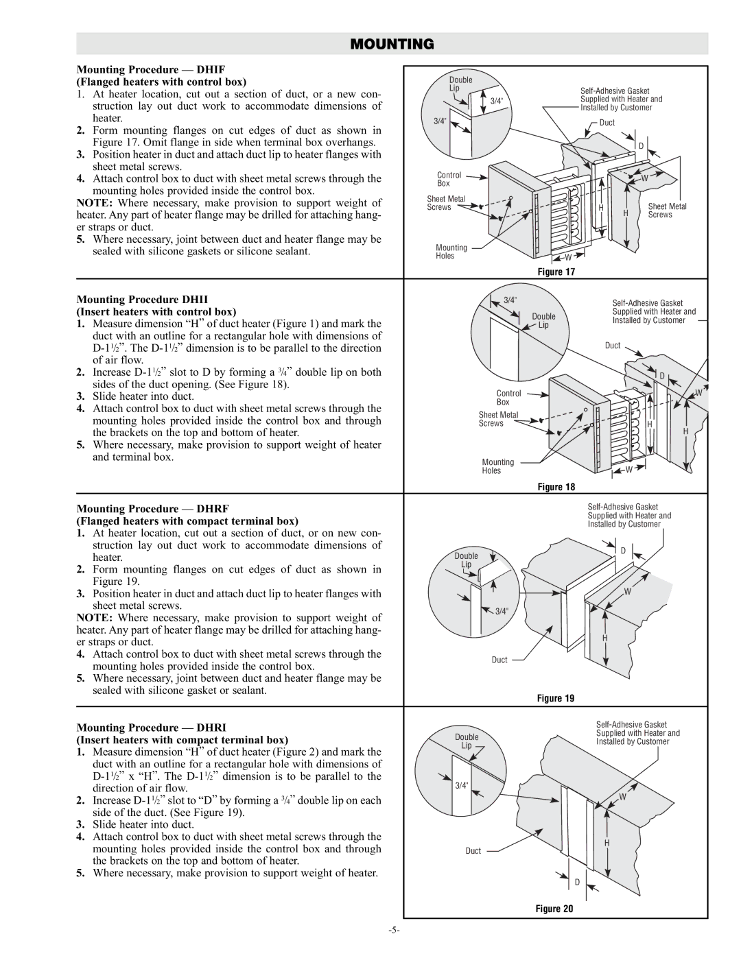
Mounting Procedure — DHIF

Double


(Flanged heaters with control box)


1. At heater location, cut out a section of duct, or a new con-

Lip

Self-Adhesive Gasket

3/4"

struction lay out duct work to accommodate dimensions of

Supplied with Heater and


Installed by Customer

heater.

3/4"

Duct


2. Form mounting flanges on cut edges of duct as shown in


Figure 17. Omit flange in side when terminal box overhangs.


D

3. Position heater in duct and attach duct lip to heater flanges with


sheet metal screws.

Control


4. Attach control box to duct with sheet metal screws through the


W

mounting holes provided inside the control box.

Box


Sheet Metal


NOTE: Where necessary, make provision to support weight of


Sheet Metal

Screws

H

H

heater. Any part of heater flange may be drilled for attaching hang-


Screws

er straps or duct.


5. Where necessary, joint between duct and heater flange may be

Mounting


sealed with silicone gaskets or silicone sealant.

W


Holes


Figure 17


Mounting Procedure DHII

3/4"


Self-Adhesive Gasket

(Insert heaters with control box)


Double

Supplied with Heater and

1. Measure dimension “H” of duct heater (Figure 1) and mark the


Installed by Customer


Lip

duct with an outline for a rectangular hole with dimensions of


Duct


D-11/2”. The D-11/2 dimension is to be parallel to the direction


of air flow.


2. Increase D-11/2 slot to D by forming a 3/4” double lip on both


D

sides of the duct opening. (See Figure 18).


Control


W

3. Slide heater into duct.


4. Attach control box to duct with sheet metal screws through the

Box


Sheet Metal


mounting holes provided inside the control box and through


Screws


H

the brackets on the top and bottom of heater.


H

5. Where necessary, make provision to support weight of heater


and terminal box.

Mounting


W


Holes


Figure 18


Mounting Procedure — DHRF


Self-Adhesive Gasket

(Flanged heaters with compact terminal box)


Supplied with Heater and


Installed by Customer

1.At heater location, cut out a section of duct, or on new con-

struction lay out duct work to accommodate dimensions of


D

heater.

Double


2. Form mounting flanges on cut edges of duct as shown in

Lip

3/4"


Figure 19.


W

3. Position heater in duct and attach duct lip to heater flanges with


sheet metal screws.


3/4"

NOTE: Where necessary, make provision to support weight of


heater. Any part of heater flange may be drilled for attaching hang-


H

er straps or duct.


4. Attach control box to duct with sheet metal screws through the


Duct

mounting holes provided inside the control box.


5.Where necessary, joint between duct and heater flange may be sealed with silicone gasket or sealant.


Figure 19

Mounting Procedure — DHRI


Self-Adhesive Gasket

(Insert heaters with compact terminal box)


Double


Supplied with Heater and


Installed by Customer

1.

Measure dimension “H” of duct heater (Figure 2) and mark the


Lip


duct with an outline for a rectangular hole with dimensions of


D-11/2 x “H”. The D-11/2 dimension is to be parallel to the

3/4"


direction of air flow.


W

2.

Increase D-11/2 slot to “D” by forming a 3/4” double lip on each


side of the duct. (See Figure 19).


3.

Slide heater into duct.


4.

Attach control box to duct with sheet metal screws through the


H


mounting holes provided inside the control box and through


Duct


the brackets on the top and bottom of heater.


5.

Where necessary, make provision to support weight of heater.


D


Figure 20


-5-


Page 5
Image 5
Chromalox PF455-3 manual Mounting Procedure Dhif

PF455-3 specifications

The Chromalox PF455-3 is a cutting-edge process feedback controller designed to optimize industrial heating applications. As part of Chromalox’s commitment to providing advanced heating solutions, the PF455-3 model stands out due to its robust features, precision control, and user-friendly design.

One of the main features of the PF455-3 is its versatile temperature control capabilities. It operates through a wide temperature range, accommodating various industrial processes that require precise thermal management. The controller employs advanced PID (Proportional, Integral, Derivative) control technology, allowing users to achieve optimal temperature settings with minimal fluctuations. This results in enhanced efficiency and productivity across heating applications.

The PF455-3 is equipped with a large, easy-to-read digital display that allows operators to monitor and adjust temperature settings effortlessly. The intuitive user interface simplifies navigation through various settings and configurations, ensuring that even less experienced personnel can operate the system with confidence. This feature significantly reduces the learning curve associated with similar devices, making it an ideal choice for diverse industries.

Additionally, the PF455-3 places a strong emphasis on safety and reliability. The device includes built-in alarm systems that notify users of any deviations from preset parameters, ensuring immediate action can be taken to prevent potential issues. The unit also features robust construction designed to withstand harsh industrial environments, providing longevity and minimizing downtime.

Moreover, the PF455-3 supports advanced communication technologies. It can be easily integrated into existing control systems via various communication protocols, including Modbus, which facilitates real-time data exchange and remote monitoring capabilities. This connectivity not only enhances operational oversight but also allows for proactive maintenance interventions.

In terms of energy efficiency, the PF455-3 excels by utilizing a unique energy-saving mode. This mode intelligently adjusts heating output based on process requirements, resulting in reduced energy consumption and lower operational costs. Users can expect significant savings on energy bills while maintaining process quality.

In summary, the Chromalox PF455-3 controller represents the forefront of industrial heating technology. With its advanced PID control, user-friendly interface, extensive safety features, and energy efficiency capabilities, it is a reliable choice for businesses looking to enhance their thermal processes. Whether in food processing, oil and gas, or chemical manufacturing, the PF455-3 stands out as a vital tool for achieving precise and efficient temperature control.