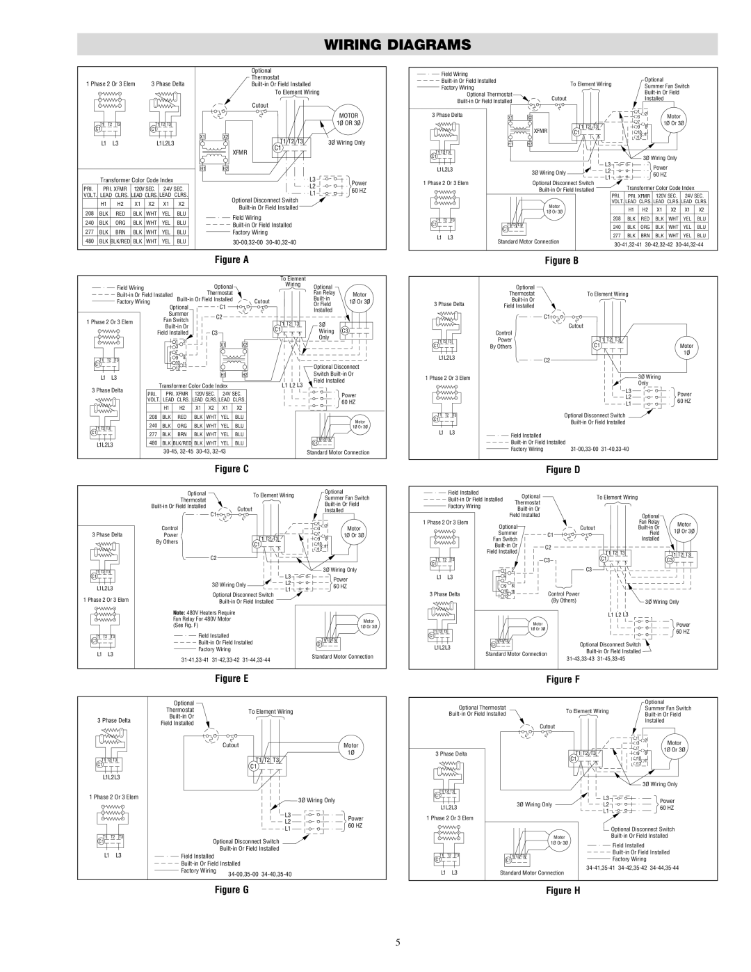
WIRING DIAGRAMS

1 Phase 2 Or 3 Elem

3 Phase Delta

Optional

Thermostat

Built-in Or Field Installed

To Element Wiring

Cutout

Field Wiring


Optional

Built-in Or Field Installed


To Element Wiring

Factory Wiring


Summer Fan Switch


Optional Thermostat

Cutout


Built-in Or Field


Installed

Built-in Or Field Installed


1


T1

T2 T3


T1 T2 T3


C1


C1


L1


L3

L1L2L3


Transformer Color Code Index

PRI.

PRI. XFMR 120V SEC. 24V SEC.

VOLT. LEAD CLRS. LEAD CLRS. LEAD CLRS.

X1

H1

X2

XFMR

H2

MOTOR

1O OR 3O

T1 T2 T3

3O Wiring Only

C1

L3

Power

L2

60 HZ

L1


3 Phase Delta

X1

X2


3

2

Motor


T1 T2 T3

7

8

1Ø Or 3Ø


XFMR

9


C1

10

11


12


H1

H2


T1 T2 T3


C1


L3


3Ø Wiring Only

L1L2L3


Power


3Ø Wiring Only

L2


60 HZ


1 Phase 2 Or 3 Elem


L1


Optional Disconnect Switch

Transformer Color Code Index


Built-in Or Field Installed


PRI.

PRI. XFMR 120V SEC. 24V SEC.


H1

H2

X1

X2

X1

X2

208

BLK

RED

BLK

WHT

YEL

BLU

240

BLK

ORG

BLK

WHT

YEL

BLU

277

BLK

BRN

BLK

WHT

YEL

BLU

480

BLK

BLK/RED BLK

WHT

YEL

BLU

Optional Disconnect Switch Built-in Or Field Installed

Field Wiring

Built-in Or Field Installed

Factory Wiring

30-00,32-00 30-40,32-40


Motor

VOLT. LEAD CLRS. LEAD

CLRS. LEAD

CLRS.


1Ø Or 3Ø


H1

H2

X1

X2

X1

X2


208

BLK

RED

BLK

WHT

YEL

BLU

T1


T2


T3


C1


T1 T2 T3


240

BLK

ORG

BLK

WHT

YEL

BLU


C1


L1

L3


277

BLK

BRN

BLK

WHT

YEL

BLU


Standard Motor Connection


30-41,32-41 30-42,32-42 30-44,32-44


Figure A

Figure B


Field Wiring


Optional


Built-in Or Field Installed


Thermostat


Built-in Or Field Installed


Factory Wiring


Optional


C1


Summer


C2


1 Phase 2 Or 3 Elem


Fan Switch


Built-in Or


Field Installed


C3


1

2


X1

X2


3


7

8


T1

T2

T3


9


10

11


C1


12


L1

L3


H1

H2


3 Phase Delta


Transformer Color Code Index


PRI.

PRI. XFMR

120V SEC.

24V SEC.


VOLT. LEAD

CLRS. LEAD CLRS. LEAD

CLRS.


H1

H2

X1

X2

X1

X2


208

BLK

RED

BLK

WHT

YEL

BLU

T1 T2 T3


240

BLK

ORG

BLK

WHT

YEL

BLU

C1


277

BLK

BRN

BLK

WHT

YEL

BLU

L1L2L3


480

BLK BLK/RED BLK

WHT

YEL

BLU


30-45, 32-45

30-43, 32-43


To Element


Wiring

Optional


Fan Relay

Motor

Cutout

Built-in

1O Or 3O

Or Field


Installed


T1 T2 T3

3O


C1

Wiring C3


Only


Optional Disconnect


Switch Built-in Or

L1 L2 L3

Field Installed


Power


60 HZ


Motor


1O Or 3O


T1 T2 T3


C1


Standard Motor Connection

3 Phase Delta

T1 T2 T3

C1

L1L2L3

1 Phase 2 Or 3 Elem

T1 T2 T3

C1

L1 L3

Optional


Thermostat

To Element Wiring


Built-in Or


Field Installed


C1


Cutout


Control

T1 T2 T3


Power


By Others

C1


Motor


1O


C2


3Ø Wiring


Only


L3

Power


L2


60 HZ


L1


Optional Disconnect Switch


Built-in Or Field Installed


Field Installed


Built-in Or Field Installed


Factory Wiring

31-00,33-00

31-40,33-40


Figure C


Optional


To Element Wiring

Optional


Summer Fan Switch


Thermostat


Built-in Or Field Installed

Cutout


Built-in Or Field


Installed


C1


Control


1

2

Motor


3

3 Phase Delta


Power


T1

T2 T3

7

8

1Ø Or 3Ø


By Others


9


C1


10

11


12


C2


T1 T2 T3


L3

3Ø Wiring Only

C1


Power


3Ø Wiring Only


L2

L1L2L3


60 HZ


L1


Optional Disconnect Switch


1 Phase 2 Or 3 Elem


Built-in Or Field Installed


Note: 480V Heaters Require


Fan Relay For 480V Motor


Motor


(See Fig. F)


1Ø Or 3Ø

T1

T2 T3

Field Installed


T1 T2 T3


C1


Built-in Or Field Installed


C1


L1

L3

Factory Wiring


31-41,33-41

31-42,33-42

31-44,33-44

Standard Motor Connection


Figure E

Figure D


Field Installed


Optional


To Element Wiring


Built-in Or Field Installed


Thermostat


Factory Wiring


Built-in Or


Field Installed


Optional


1 Phase 2 Or 3 Elem

Optional


Fan Relay

Motor


Cutout


Built-in Or


1O Or 3O


Summer

C1


Field


Fan Switch


Installed


Built-in Or

C2


Field Installed


T1

T2 T3


T1 T2 T3


C1


T1

T2

T3


C3


C3

C1


C3


1

2


L1


L3

3


7


9

8


3 Phase Delta

10

11

Control Power


12


(By Others)


3O Wiring Only


L1 L2 L3


Motor


Power

T1 T2 T3


1O Or 3O


60 HZ

C1


T1 T2 T3


Optional Disconnect Switch


L1L2L3

C1


Standard Motor Connection

Built-in Or Field Installed


31-45,33-45


31-43,33-43


Figure F

3 Phase Delta

T1 T2 T3

C1

L1L2L3

1 Phase 2 Or 3 Elem

T1 T2 T3

C1

L1 L3

Optional


Thermostat

To Element Wiring

Built-in Or


Field Installed


Cutout

Motor

T1 T2 T3

C1


3Ø Wiring Only


L3

Power


L2


60 HZ


L1


Optional Disconnect Switch


Built-in Or Field Installed


Field Installed


Built-in Or Field Installed


Factory Wiring

34-00,35-00 34-40,35-40


Optional Thermostat


Optional


To Element Wiring

Summer Fan Switch


Built-in Or Field Installed

Built-in Or Field


Cutout


Installed


1

2

Motor


3


3 Phase Delta


T1 T2 T3

7

8

1Ø Or 3Ø


9


C1

10

11


12


3Ø Wiring Only

T1 T2 T3


C1


L3


Power


L1L2L3


3Ø Wiring Only

L2


60 HZ


L1


1 Phase 2 Or 3 Elem


Optional Disconnect Switch


Motor

Built-in Or Field Installed


1Ø Or 3Ø

Field Installed


T1

T2 T3


T1 T2 T3

Built-in Or Field Installed


Factory Wiring


C1


C1


L1

L3


34-41,35-41 34-42,35-42 34-44,35-44

Standard Motor Connection


Figure G

Figure H

5

Page 5
Image 5
Chromalox PF479-6 dimensions Wiring Diagrams

PF479-6 specifications

The Chromalox PF479-6 is a state-of-the-art electric heater that exemplifies the company’s commitment to providing high-quality thermal solutions for various industrial applications. Known for its reliability and efficiency, this heater boasts several features and technologies that set it apart in the market.

One of the standout characteristics of the PF479-6 is its robust construction. Designed to withstand harsh environments, it is built with durable materials that offer high resistance to corrosion and wear. This makes it ideal for use in facilities where exposure to chemicals or extreme temperatures is common. The heater is compact, making it easy to install in tight spaces while still providing powerful heating capabilities.

The PF479-6 employs advanced heating technologies that ensure consistent and efficient heat output. It uses a high-performance heating element that allows for rapid heating and excellent temperature control. The heater operates quietly, providing an unobtrusive solution for heating applications in offices, manufacturing plants, and anywhere heat is necessary without added noise.

Temperature control is enhanced through built-in safety features, including thermal limit controls. These mechanisms prevent overheating, ensuring both the longevity of the unit and safety for users. Additionally, the PF479-6 is equipped with user-friendly controls that make operation straightforward, allowing personnel to adjust settings quickly as needed.

Energy efficiency is another critical aspect of the Chromalox PF479-6. It is designed to reduce energy consumption while still delivering optimal heating performance. This not only helps in lowering operational costs but also aligns with environmental standards by minimizing carbon footprints.

Moreover, the heater’s versatility is showcased through its compatibility with various applications, including process heating, space heating, and equipment heating. Its adaptability makes it a go-to choice for industries such as food processing, pharmaceuticals, and petrochemicals.

In conclusion, the Chromalox PF479-6 is a premier electric heater that combines durable construction, advanced heating technologies, and energy efficiency to meet the diverse needs of various industries. Its reliability and performance make it an essential asset for any organization seeking effective thermal solutions. With its focus on safety, ease of use, and adaptability, the PF479-6 is poised to provide years of dependable service.