|
|
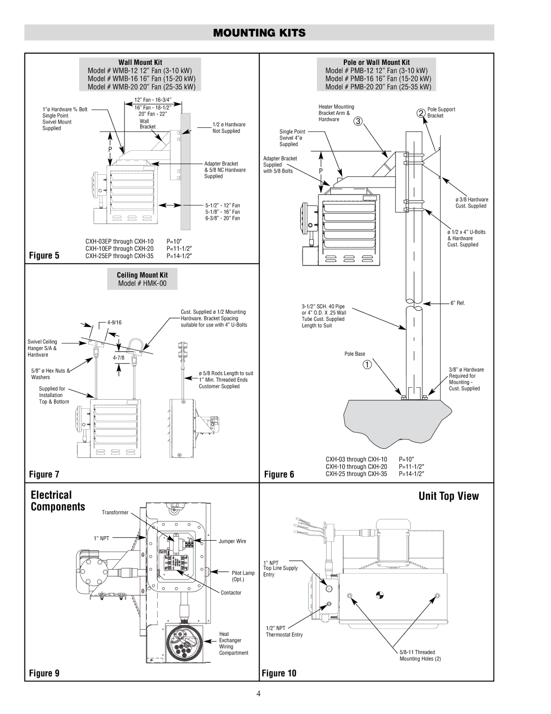
| MOUNTING KITS |
|
| ||
|
| Wall Mount Kit |
|
| Pole or Wall Mount Kit |
| |
|
| Model # |
| Model # | |||
|
| Model # |
| Model # | |||
|
| Model # |
| Model # | |||
|
| 12” Fan - |
|
|
|
| |
1”ø Hardware % Bolt | 16” Fan - |
| Heater Mounting | Pole Support | |||
Single Point |
| 20” Fan - 22” |
| Bracket Arm & | ➂ | ➁ Bracket | |
Swivel Mount |
| Wall | 1/2 ø Hardware |
| Hardware |
| |
|
|
|
| ||||
Supplied |
| Bracket | Not Supplied | Single Point |
|
| |
|
|
|
|
| |||
|
|
|
| Swivel 4”ø |
|
| |
|
| P |
| Supplied |
|
|
|
|
|
|
|
|
|
| |
|
|
| Adapter Bracket | Adapter Bracket |
|
|
|
|
|
| Supplied |
|
|
| |
|
|
| & 5/8 NC Hardware | with 5/8 Bolts | P |
|
|
|
|
| Supplied |
|
|
|
|
|
|
|
|
|
| ø 3/8 Hardware | |
|
|
|
|
|
| Cust. Supplied | |
|
|
|
|
|
|
| |
|
|
|
|
|
|
| |
|
|
|
|
|
|
| ø 1/2 x 4” |
| P=10” |
|
|
| & Hardware | ||
|
|
|
| Cust. Supplied | |||
|
|
|
| ||||
Figure 5 |
|
|
|
| |||
|
|
|
| ||||
|
| Ceiling Mount Kit |
|
|
|
| |
|
| Model # |
|
|
|
|
|
|
|
|
|
|
| 6” Ref. | |
|
|
| Cust. Supplied ø 1/2 Mounting |
|
|
| |
|
|
|
| or 4” O.D. X .25 Wall |
|
| |
|
| Hardware. Bracket Spacing |
| Tube Cust. Supplied |
|
| |
|
| suitable for use with 4” |
| Length to Suit |
|
| |
|
|
|
|
|
| ||
Swivel Ceiling |
|
|
|
|
|
|
|
Hanger S/A & |
|
|
|
| Pole Base |
| |
Hardware |
|
|
|
| |||
|
|
|
|
| ➀ |
| |
5/8” ø Hex Nuts & |
|
| ø 5/8 Rods Length to suit |
|
| 3/8” ø Hardware | |
|
|
|
|
| |||
Washers |
|
|
|
|
| Required for | |
|
| 1” Min. Threaded Ends |
|
|
| ||
|
|
|
|
|
| Mounting - | |
|
|
| Customer Supplied |
|
|
| |
Supplied for |
|
|
|
|
| Cust. Supplied | |
|
|
|
|
|
| ||
Installation |
|
|
|
|
|
|
|
Top & Bottom |
|
|
|
|
|
|
|
|
|
|
|
|
|
|
|
|
|
|
|
|
|
|
|
|
|
|
|
|
|
|
|
|
|
|
|
|
|
|
|
|
|
|
|
|
| P=10” | |
|
|
|
|
|
|
|
|
|
|
|
|
|
|
|
|
|
|
|
|
|
|
|
|
|
|
|
|
|
|
|
|
|
|
|
|
|
| ||
|
|
|
|
|
|
|
|
|
|
|
|
|
|
|
|
|
|
|
|
|
|
|
|
|
|
|
|
|
|
|
|
|
|
|
|
|
| ||
|
|
|
|
|
|
|
|
|
|
|
|
|
|
|
|
|
|
|
|
|
|
|
|
|
|
|
|
|
|
|
|
|
|
|
|
|
| ||
|
|
|
|
|
|
|
|
|
|
|
|
|
|
|
|
|
|
|
|
|
|
|
|
|
|
|
|
|
|
|
|
|
|
|
|
|
| ||
|
|
|
|
|
|
|
|
|
|
|
|
|
|
|
|
|
|
|
|
|
|
|
|
|
|
|
|
|
|
|
|
|
|
|
|
|
| ||
|
|
|
|
|
|
|
|
|
|
|
|
|
|
|
|
|
|
|
|
|
|
|
|
|
|
|
|
|
|
|
|
|
|
|
|
|
| ||
|
|
|
|
|
|
|
|
|
|
|
|
|
|
|
|
|
|
|
|
|
|
|
|
|
|
|
|
|
|
|
|
|
|
|
|
|
| ||
|
|
|
|
|
|
|
|
|
|
|
|
|
|
|
|
|
|
|
|
|
|
|
|
|
|
|
|
|
|
|
|
|
|
|
|
|
| ||
Figure 7 |
|
|
|
|
|
|
|
|
|
|
|
|
|
|
|
|
|
|
|
|
|
|
|
|
|
|
|
|
|
|
|
|
|
|
| Figure 6 | |||
|
|
|
|
|
|
|
|
|
|
|
|
|
|
|
|
|
|
|
|
|
|
|
|
|
|
|
|
|
|
|
|
|
|
| |||||
Electrical |
| Unit Top View |
Components |
|
|
Transformer |
|
|
1” NPT | Jumper Wire |
|
|
| |
|
| 1” NPT |
| Pilot Lamp | Top Line Supply |
| Entry | |
| (Opt.) |
|
| Contactor |
|
| Heat | 1/2” NPT |
| Thermostat Entry | |
| Exchanger |
|
| Wiring | |
| Compartment | |
|
| Mounting Holes (2) |
Figure 9 |
| Figure 10 |
4