Figure 12
Dial
Stop Post
Stop
Tab

WIRING

Figure 6

4.Remove white shaft coupler for safe-keeping while making wiring connections (see Figure 6).

5.Connect wires according to wiring diagrams (Figures 7 thru 11). Note: Electrical connections should be made with generous loops of wire — approximately 6” per lead.

6.Replace white shaft coupler.

7. WARNING: It is possible to replace enclosure cover with adjustment knob 180 rotational degrees out of alignment resulting in large cali- bration errors. To avoid this, carefully follow these procedures.

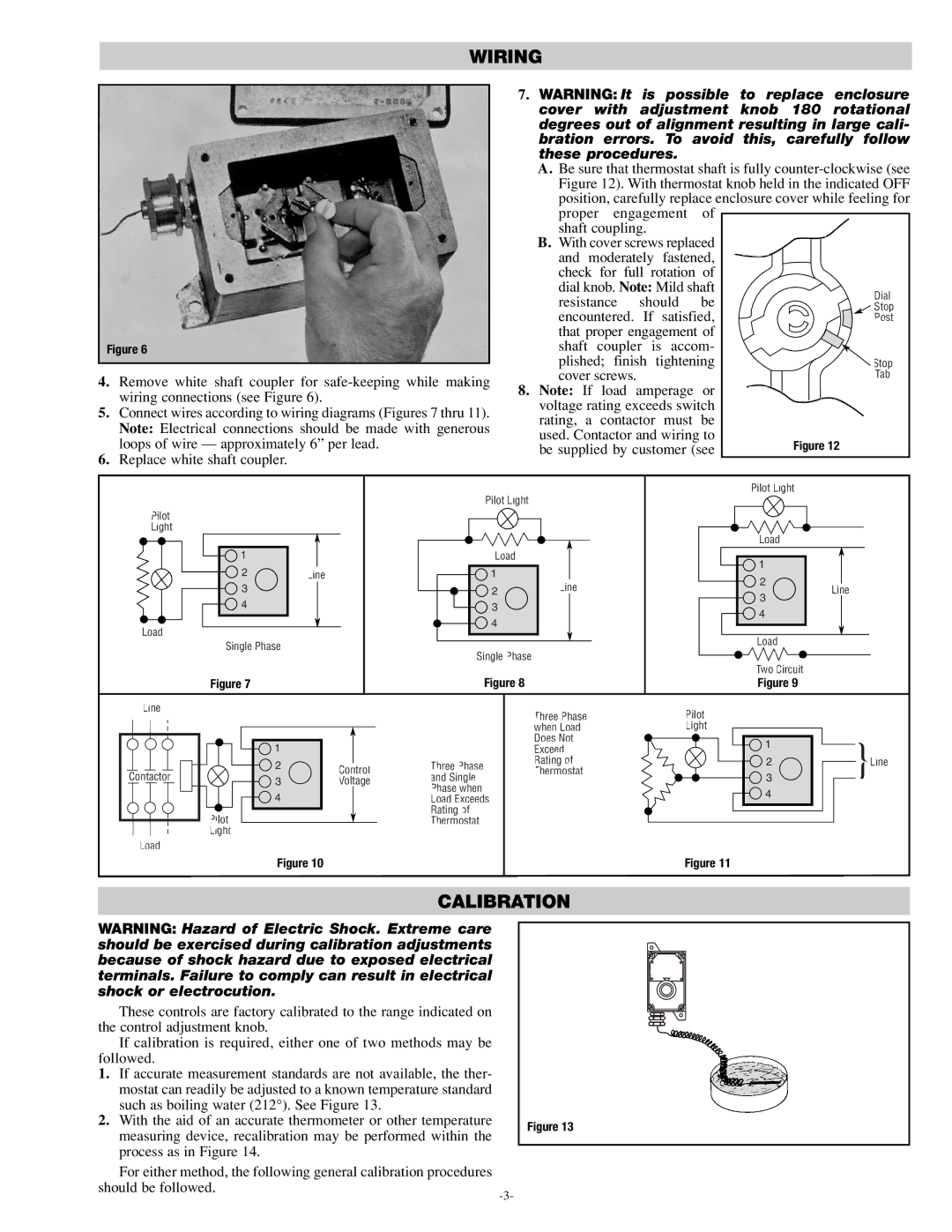
A. Be sure that thermostat shaft is fully counter-clockwise (see Figure 12). With thermostat knob held in the indicated OFF position, carefully replace enclosure cover while feeling for proper engagement of

shaft coupling.

B. With cover screws replaced and moderately fastened, check for full rotation of dial knob. Note: Mild shaft resistance should be

encountered. If satisfied, that proper engagement of

shaft coupler is accom- plished; finish tightening

cover screws.

8.Note: If load amperage or voltage rating exceeds switch

rating, a contactor must be used. Contactor and wiring to be supplied by customer (see


Pilot Light


Pilot Light


Pilot


Light


Load


1


Load


1


2

Line

1


Line

2


3


2

Line


3


4


3


4


4


Load


Load


Single Phase


Single Phase


Two Circuit


Figure 7


Figure 8


Figure 9


Line


Three Phase

Pilot


when Load

Light


1


Does Not

1

}


Exceed


2

Control

Three Phase

Rating of

2

Line

Contactor

Thermostat

3


3

Voltage

and Single


4


Phase when


4


Load Exceeds


Pilot


Rating of


Thermostat


Light


Load


Figure 10


Figure 11


CALIBRATION

WARNING: Hazard of Electric Shock. Extreme care should be exercised during calibration adjustments because of shock hazard due to exposed electrical terminals. Failure to comply can result in electrical shock or electrocution.

These controls are factory calibrated to the range indicated on the control adjustment knob.

If calibration is required, either one of two methods may be followed.

1.If accurate measurement standards are not available, the ther- mostat can readily be adjusted to a known temperature standard such as boiling water (212°). See Figure 13.

2.With the aid of an accurate thermometer or other temperature measuring device, recalibration may be performed within the process as in Figure 14.

For either method, the following general calibration procedures should be followed.

-3-

Figure 13

Page 3
Image 3
Chromalox PK413-4 specifications Calibration

PK413-4 specifications

The Chromalox PK413-4 is a highly versatile electric heater designed to provide efficient heating solutions in various industrial and commercial applications. Renowned for its durable construction and advanced technology, the PK413-4 is engineered to deliver reliable performance while ensuring safety and compliance with industry standards.

One of the main features of the Chromalox PK413-4 is its modular design, which allows for easy installation and maintenance. The heater's flexibility enables it to be configured for different heating requirements, whether for process heat, air heating, or even freeze protection. This adaptability makes it suitable for use in diverse environments, from manufacturing facilities to food processing plants.

The PK413-4 utilizes robust industrial-grade heating elements made from high-quality materials, ensuring long-lasting operation even in harsh conditions. It boasts a stainless steel sheath, providing excellent resistance to corrosion and enhancing its overall lifespan. This feature is particularly important in industries where exposure to moisture or chemicals is prevalent.

Another significant characteristic of the Chromalox PK413-4 is its energy efficiency. The heater is designed to minimize energy consumption while maximizing heat output. This efficiency not only contributes to cost savings but also promotes environmental sustainability by reducing the carbon footprint associated with energy use.

In terms of technology, the PK413-4 incorporates advanced control systems that allow for precise temperature regulation. Users can easily set and adjust temperature settings, ensuring optimal heating without unnecessary energy expenditure. The integration of digital controls enables real-time monitoring and diagnostics, making it easier for operators to maintain ideal operating conditions.

Safety features are paramount in the PK413-4's design. It includes built-in over-temperature protection and limit controls to prevent overheating and potential hazards. The heater is also designed to comply with various safety regulations and standards, providing peace of mind to users regarding operational safety.

Overall, the Chromalox PK413-4 stands out as a reliable and effective heating solution. Its robust construction, energy efficiency, and advanced control technology make it an ideal choice for a wide range of applications. Whether in harsh industrial settings or sensitive commercial environments, the PK413-4 provides consistent heating performance and durability, making it a trusted choice for engineers and facility managers alike.