WIRING

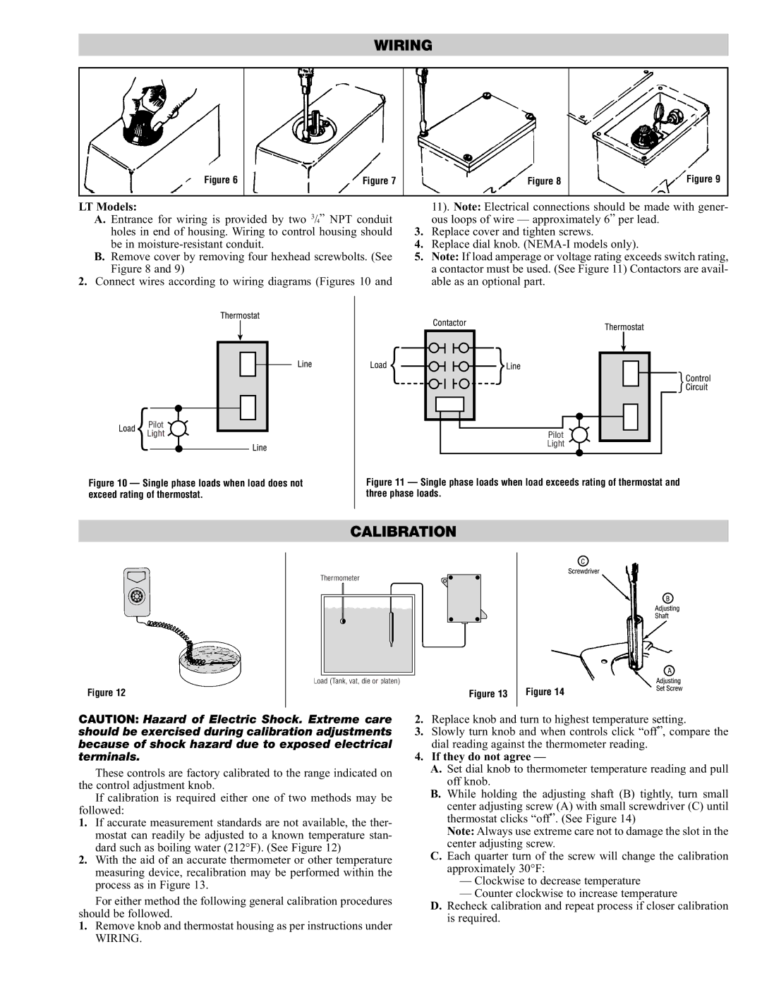
Figure 6

Figure 7

Figure 8

Figure 9

LT Models:


11). Note: Electrical connections should be made with gener-

A. Entrance for wiring is provided by two 3/4” NPT conduit


ous loops of wire — approximately 6” per lead.

holes in end of housing. Wiring to control housing should

3.

Replace cover and tighten screws.

be in moisture-resistant conduit.

4.

Replace dial knob. (NEMA-I models only).

B.Remove cover by removing four hexhead screwbolts. (See 5. Note: If load amperage or voltage rating exceeds switch rating,

Figure 8 and 9)

a contactor must be used. (See Figure 11) Contactors are avail-

2. Connect wires according to wiring diagrams (Figures 10 and

able as an optional part.

Pilot

Light

Figure 10 — Single phase loads when load does not exceed rating of thermostat.

Pilot

Light

Figure 11 — Single phase loads when load exceeds rating of thermostat and three phase loads.

CALIBRATION

Figure 12

Thermometer

Load (Tank, vat, die or platen)

Figure 13

Figure 14

CAUTION: Hazard of Electric Shock. Extreme care should be exercised during calibration adjustments because of shock hazard due to exposed electrical terminals.

These controls are factory calibrated to the range indicated on the control adjustment knob.

If calibration is required either one of two methods may be followed:

1.If accurate measurement standards are not available, the ther- mostat can readily be adjusted to a known temperature stan- dard such as boiling water (212°F). (See Figure 12)

2.With the aid of an accurate thermometer or other temperature measuring device, recalibration may be performed within the process as in Figure 13.

For either method the following general calibration procedures should be followed.

1.Remove knob and thermostat housing as per instructions under

WIRING.

2.Replace knob and turn to highest temperature setting.

3.Slowly turn knob and when controls click “off”, compare the dial reading against the thermometer reading.

4.If they do not agree —

A.Set dial knob to thermometer temperature reading and pull off knob.

B.While holding the adjusting shaft (B) tightly, turn small center adjusting screw (A) with small screwdriver (C) until thermostat clicks “off”. (See Figure 14)

Note: Always use extreme care not to damage the slot in the center adjusting screw.

C.Each quarter turn of the screw will change the calibration approximately 30°F:

Clockwise to decrease temperature

Counter clockwise to increase temperature

D.Recheck calibration and repeat process if closer calibration is required.

Page 3
Image 3
Chromalox PK425-2 specifications Calibration, LT Models, If they do not agree

PK425-2 specifications

The Chromalox PK425-2 is an advanced unit in the realm of industrial heating solutions, specifically designed for various heating applications. Known for its precision and reliability, this product is widely utilized in industries ranging from food processing and chemical manufacturing to oil and gas.

One of the standout features of the PK425-2 is its high-performance heating element, which is engineered for excellent thermal efficiency. The device incorporates robust construction materials and cutting-edge design, which work together to optimize heat transfer. This ensures that the desired temperatures are achieved quickly and maintained consistently, crucial for processes that require strict temperature control.

In addition to its heating capabilities, the PK425-2 boasts sophisticated temperature control technology. It is compatible with temperature controllers, allowing users to fine-tune operational settings for specific applications. This versatility enables it to cater to a wide array of processes, from simple to complex heating requirements. The seamless integration of controller systems helps in better monitoring and can lead to significant energy savings.

Safety is another critical aspect of the PK425-2 design. It comes equipped with built-in safety features, including over-temperature protection and safety shutoff mechanisms. These features not only ensure safe operation during high-demand scenarios but also enhance the overall longevity of the unit.

Durability is a hallmark of the PK425-2. The unit is constructed from materials that withstand harsh industrial environments, making it highly durable and resistant to corrosion and wear. This longevity decreases maintenance needs, providing a cost-effective solution for businesses looking to minimize downtime and operational expenses.

Efficiency is a crucial characteristic of the Chromalox PK425-2, resulting in reduced energy consumption without compromising on performance. This not only lowers operational costs but also aligns with modern sustainability goals.

In summary, the Chromalox PK425-2 stands out in the industrial heating market with its combination of high-performance heating elements, advanced temperature control technology, built-in safety features, and premium durability. These characteristics make it a reliable choice for industries requiring consistent and efficient heating solutions, solidifying its reputation as a superior product in its category.