GENERAL
The Chromalox Horizontal Electric Vaporizer is a thoroughly engineered
Model CHTVX, Class 1, Group D, Division 1 is
INSTALLATION
CAUTION: This vaporizer is not for use with water or ethylene glycol and water mixtures as the heat transfer media. Check with your local Chromalox Sales and Application Engineer to be sure that you are using an accepted heat transfer media in this vapor- izer or consult PQ301.
Note: When installing the vaporizer, allow a minimum of 3 feet for removing heating element if, and when, necessary.
HYDRAULIC OR MECHANICAL:
Note: The CHTVW vaporizer should be mounted so that the con- trol box does not fall in direct sunlight.
The bed plate should be mounted on solid foundation, prefer- ably level.
The pipe lines from the Chromalox vaporizer to the process should be the same size as the vaporizer’s piping connections. All piping should be arranged so that the vaporizer is not subject to extreme nozzle loading due to thermal expansion and contraction of pipe lines. If these instructions are not followed, cracks could devel- op in the vaporizer where the inlet and outlet nozzles are attached.
1.The piping of the entire system should be arranged to minimize pockets where air may be trapped. Manual air vents or bleeder valves should be provided at all high points in the system and every time the flow of the condensate has to drop.
2.Condensate return systems:
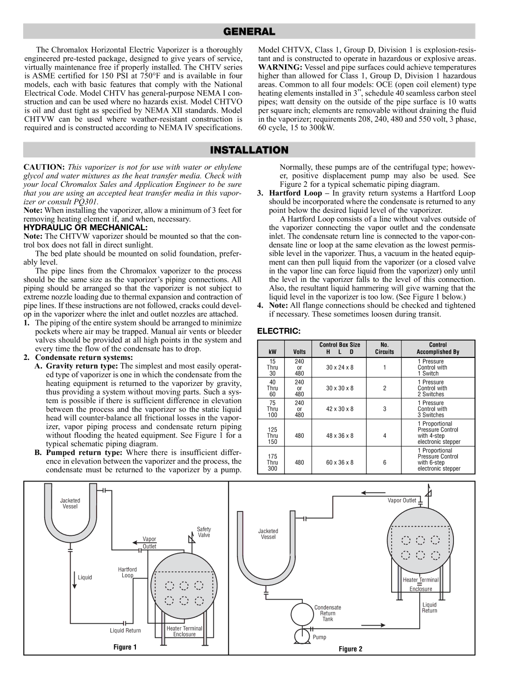
A.Gravity return type: The simplest and most easily operat- ed type of vaporizer is one in which the condensate from the heating equipment is returned to the vaporizer by gravity, thus providing a system without moving parts. Such a sys- tem is possible if there is sufficient difference in elevation between the process and the vaporizer so the static liquid head will
B.Pumped return type: Where there is insufficient differ- ence in elevation between the vaporizer and the process, the condensate must be returned to the vaporizer by a pump.
Normally, these pumps are of the centrifugal type; howev- er, positive displacement pump may also be used. See Figure 2 for a typical schematic piping diagram.
3.Hartford Loop – In gravity return systems a Hartford Loop should be incorporated where the condensate is returned to any point below the desired liquid level of the vaporizer.
A Hartford Loop consists of a line without valves outside of the vaporizer connecting the vapor outlet and the condensate inlet. The condensate return line is connected to the
4.Note: All flange connections should be checked and tightened if necessary. These sometimes loosen during transit.
ELECTRIC:
|
| Control Box Size | No. |
| Control |
kW | Volts | H L D | Circuits | Accomplished By | |
15 | 240 |
|
| 1 | Pressure |
Thru | or | 30 x 24 x 8 | 1 | Control with | |
30 | 480 |
|
| 1 | Switch |
40 | 240 |
|
| 1 | Pressure |
Thru | or | 30 x 30 x 8 | 2 | Control with | |
60 | 480 |
|
| 2 | Switches |
75 | 240 |
|
| 1 | Pressure |
Thru | or | 42 x 30 x 8 | 3 | Control with | |
100 | 480 |
|
| 3 | Switches |
|
|
|
| 1 | Proportional |
125 |
|
|
| Pressure Control | |
Thru | 480 | 48 x 36 x 8 | 4 | with | |
150 |
|
|
| electronic stepper | |
|
|
|
| 1 | Proportional |
175 |
|
|
| Pressure Control | |
Thru | 480 | 60 x 36 x 8 | 6 | with | |
300 |
|
|
| electronic stepper | |
Jacketed |
|
|
|
| Vapor Outlet |
Vessel |
|
|
|
|
|
|
|
| Safety | Jacketed |
|
|
|
| Valve |
| |
|
| Vapor | Vessel |
| |
|
|
|
| ||
|
|
|
|
| |
|
| Outlet |
|
|
|
| Hartford |
|
|
|
|
Liquid | Loop |
|
|
| Heater Terminal |
|
|
|
| ||
|
|
|
|
| |
|
|
|
|
| Enclosure |
|
|
|
| Condensate | Liquid |
|
|
|
| Return | |
|
|
|
| Return | |
|
|
|
|
| |
|
|
|
| Tank |
|
| Liquid Return |
| Heater Terminal |
|
|
|
| Enclosure | Pump |
| |
|
|
|
| ||
|
|
|
|
| |
| Figure 1 |
|
| Figure 2 |
|