S-RAD-2 specifications
Chromalox S-RAD-2 is an advanced heating solution that exemplifies innovation in the field of electric heating technology. This device is specifically engineered to provide efficient and reliable heating for a variety of industrial applications. One of the standout features of the S-RAD-2 is its superior heating performance, achieved through advanced materials and design elements that ensure optimal thermal efficiency.The S-RAD-2 utilizes radiant heating technology, which allows for quicker heat up times and reduced energy consumption compared to traditional convection heating methods. By delivering heat directly to surfaces and objects rather than heating the air, the S-RAD-2 minimizes heat loss and ensures that the energy used is maximized effectively.
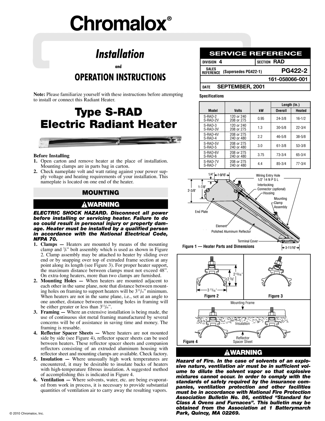
Another key characteristic of the S-RAD-2 is its versatility. This heating solution can be employed in various environments, from manufacturing facilities to commercial kitchens. The design allows for mounting flexibility, with options for wall, ceiling, or even portable configurations, making it suitable for different spatial constraints and operational needs.
The S-RAD-2 is built with durability in mind. It incorporates robust materials that can withstand the rigors of industrial use while maintaining consistent performance over time. Its weather-resistant features further extend its applicability in outdoor settings or environments subject to moisture.
Safety is also a primary focus with the S-RAD-2. Equipped with advanced safety controls, the unit prevents overheating and ensures that operations remain within safe limits. Additionally, compliance with industry standards and regulations guarantees that the device meets rigorous safety requirements, instilling confidence in its use across various sectors.
Ease of installation and maintenance is another hallmark of the S-RAD-2. The equipment is designed for straightforward installation, minimizing setup time and costs. Maintenance procedures are simplified, promoting operational efficiency and reducing downtime.
Lastly, the S-RAD-2 integrates seamlessly with modern control systems, allowing for programmable settings and smart connectivity options that enable users to optimize heating schedules and reduce overall energy usage. The combination of these features makes the Chromalox S-RAD-2 a preferred choice for industries looking to enhance productivity while ensuring safety and efficiency.