Chromalox S-RAD-2 specifications Wiring, Operation, Before energizing this heater

Models: S-RAD-2

1 4
Download 4 pages 43.65 Kb
Page 2
Image 2
WIRING

WIRING

ELECTRIC SHOCK HAZARD. Any installation involv- ing electric heaters must be performed by a quali- fied person and must be effectively grounded in accordance with the National Electrical Code to eliminate shock hazard.

1.Electrical connection to the Radiant Heater is made through one opening tapped for 1/2” connector. Opening is in the top of the extruded heater housing, near the terminal end.

2.Wiring should be run in flexible or rigid metal conduit and must be installed in accordance with local codes and the National Electrical Code by a qualified person.

CAUTION: High temperatures will oxidize cop- per. Do not use copper wire in connecting this heater. Insulated, nickel-plated copper wire is recommended.

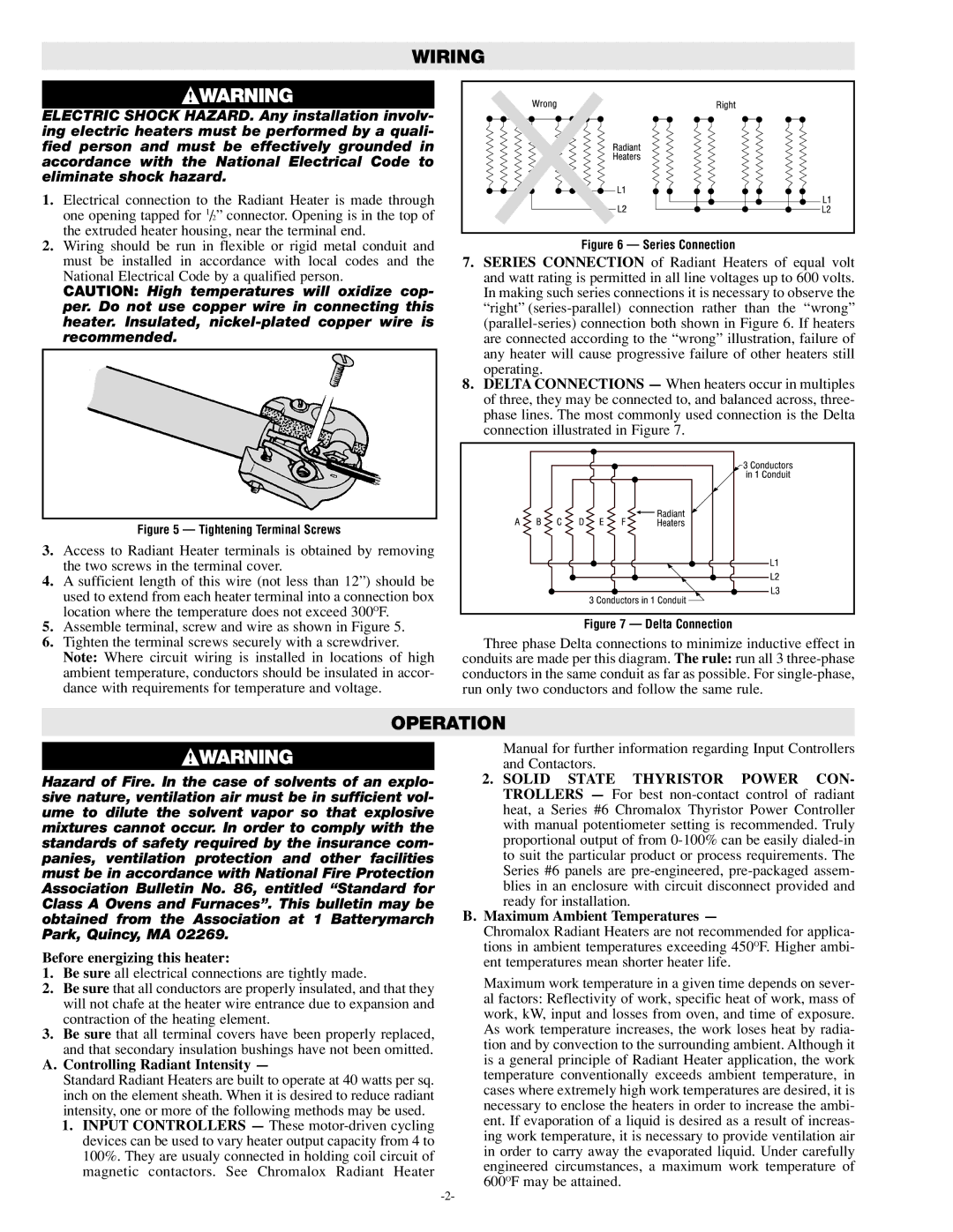
Figure 6 — Series Connection

7.SERIES CONNECTION of Radiant Heaters of equal volt and watt rating is permitted in all line voltages up to 600 volts. In making such series connections it is necessary to observe the “right” (series-parallel) connection rather than the “wrong” (parallel-series) connection both shown in Figure 6. If heaters are connected according to the “wrong” illustration, failure of any heater will cause progressive failure of other heaters still operating.

8.DELTACONNECTIONS — When heaters occur in multiples of three, they may be connected to, and balanced across, three- phase lines. The most commonly used connection is the Delta connection illustrated in Figure 7.

Figure 5 — Tightening Terminal Screws

3.Access to Radiant Heater terminals is obtained by removing the two screws in the terminal cover.

4.A sufficient length of this wire (not less than 12”) should be used to extend from each heater terminal into a connection box location where the temperature does not exceed 300OF.

5.Assemble terminal, screw and wire as shown in Figure 5.

6.Tighten the terminal screws securely with a screwdriver. Note: Where circuit wiring is installed in locations of high ambient temperature, conductors should be insulated in accor- dance with requirements for temperature and voltage.

Figure 7 — Delta Connection

Three phase Delta connections to minimize inductive effect in conduits are made per this diagram. The rule: run all 3 three-phase conductors in the same conduit as far as possible. For single-phase, run only two conductors and follow the same rule.

OPERATION

Hazard of Fire. In the case of solvents of an explo- sive nature, ventilation air must be in sufficient vol- ume to dilute the solvent vapor so that explosive mixtures cannot occur. In order to comply with the standards of safety required by the insurance com- panies, ventilation protection and other facilities must be in accordance with National Fire Protection Association Bulletin No. 86, entitled “Standard for Class A Ovens and Furnaces”. This bulletin may be obtained from the Association at 1 Batterymarch Park, Quincy, MA 02269.

Before energizing this heater:

1.Be sure all electrical connections are tightly made.

2.Be sure that all conductors are properly insulated, and that they will not chafe at the heater wire entrance due to expansion and contraction of the heating element.

3.Be sure that all terminal covers have been properly replaced,

and that secondary insulation bushings have not been omitted.

A.Controlling Radiant Intensity —

Standard Radiant Heaters are built to operate at 40 watts per sq. inch on the element sheath. When it is desired to reduce radiant intensity, one or more of the following methods may be used.

1.INPUT CONTROLLERS — These motor-driven cycling devices can be used to vary heater output capacity from 4 to 100%. They are usualy connected in holding coil circuit of magnetic contactors. See Chromalox Radiant Heater

Manual for further information regarding Input Controllers and Contactors.

2.SOLID STATE THYRISTOR POWER CON- TROLLERS — For best non-contact control of radiant heat, a Series #6 Chromalox Thyristor Power Controller with manual potentiometer setting is recommended. Truly proportional output of from 0-100% can be easily dialed-in to suit the particular product or process requirements. The Series #6 panels are pre-engineered,pre-packaged assem- blies in an enclosure with circuit disconnect provided and ready for installation.

B.Maximum Ambient Temperatures —

Chromalox Radiant Heaters are not recommended for applica- tions in ambient temperatures exceeding 450OF. Higher ambi- ent temperatures mean shorter heater life.

Maximum work temperature in a given time depends on sever- al factors: Reflectivity of work, specific heat of work, mass of work, kW, input and losses from oven, and time of exposure. As work temperature increases, the work loses heat by radia- tion and by convection to the surrounding ambient. Although it is a general principle of Radiant Heater application, the work temperature conventionally exceeds ambient temperature, in cases where extremely high work temperatures are desired, it is necessary to enclose the heaters in order to increase the ambi- ent. If evaporation of a liquid is desired as a result of increas- ing work temperature, it is necessary to provide ventilation air in order to carry away the evaporated liquid. Under carefully engineered circumstances, a maximum work temperature of 600OF may be attained.

-2-

Page 2
Image 2
Chromalox S-RAD-2 specifications Wiring, Operation, Before energizing this heater, A.Controlling Radiant Intensity