Manuals
/
Cisco Systems
/
Computer Equipment
/
Network Router
Cisco Systems
1721
manual
Back Panel Ports and LEDs, Connector/Slot, Label/Color, Description
Models:
1721
1
4
10
10
Download
10 pages
1.58 Kb
1
2
3
4
5
6
7
8
Connector/Slot
How to
Key Features
Page 4
Image 4
Page 3
Page 5
Page 4
Image 4
Page 3
Page 5
Contents
Key Features Back Panel Ports and LEDs Front Panel LEDs Router Memory
Unpacking the Router Additional Required Equipment
Cisco 1721 Router Hardware Installation Guide
Cisco 1721 Router Overview
Key Features
Figure 1-1 Cisco 1721 Router
Feature
Description
Connector/Slot
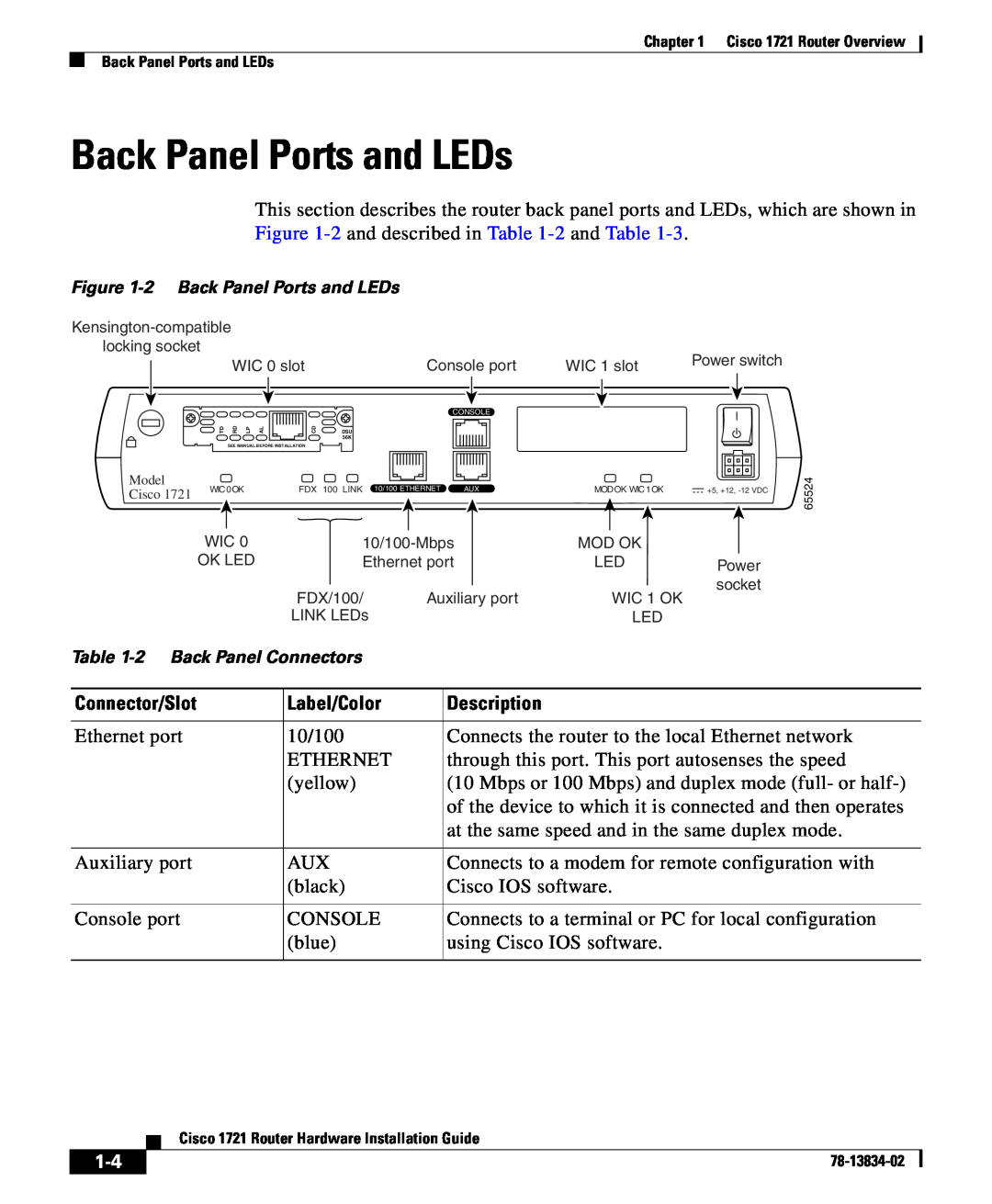
Back Panel Ports and LEDs
Label/Color
Table 1-2 Back Panel Connectors
to the Cisco WAN Interface Cards Hardware Installation
Front Panel LEDs
LED Label
Color
Figure 1-3 Front Panel LEDs
See the section “OK LED Diagnostics” in Chapter
Table 1-4 Front Panel LEDs
Router Memory
Table 1-4 Front Panel LEDs continued
Types of Memory
Amounts of Memory
Unpacking the Router
Additional Required Equipment
When You Use It
Equipment
types, refer to the Cisco WAN Interface Cards Hardware
1-10
Top
Page
Image
Contents