Chapter 1 Overview
The Cisco CWDM SFPs operate on
http://www.cisco.com/en/US/products/hw/modules/ps4999/products_device_support_table09186a00803bf095.html
Also see your SFP module documentation and the Cisco Small
For the latest information about SFP modules supported by the switch, see the release notes.
Cable Guard
You can order an optional cable guard to secure cables to the front of the switch and prevent them from being accidentally removed. To order a cable guard, contact your Cisco representative.
LEDs
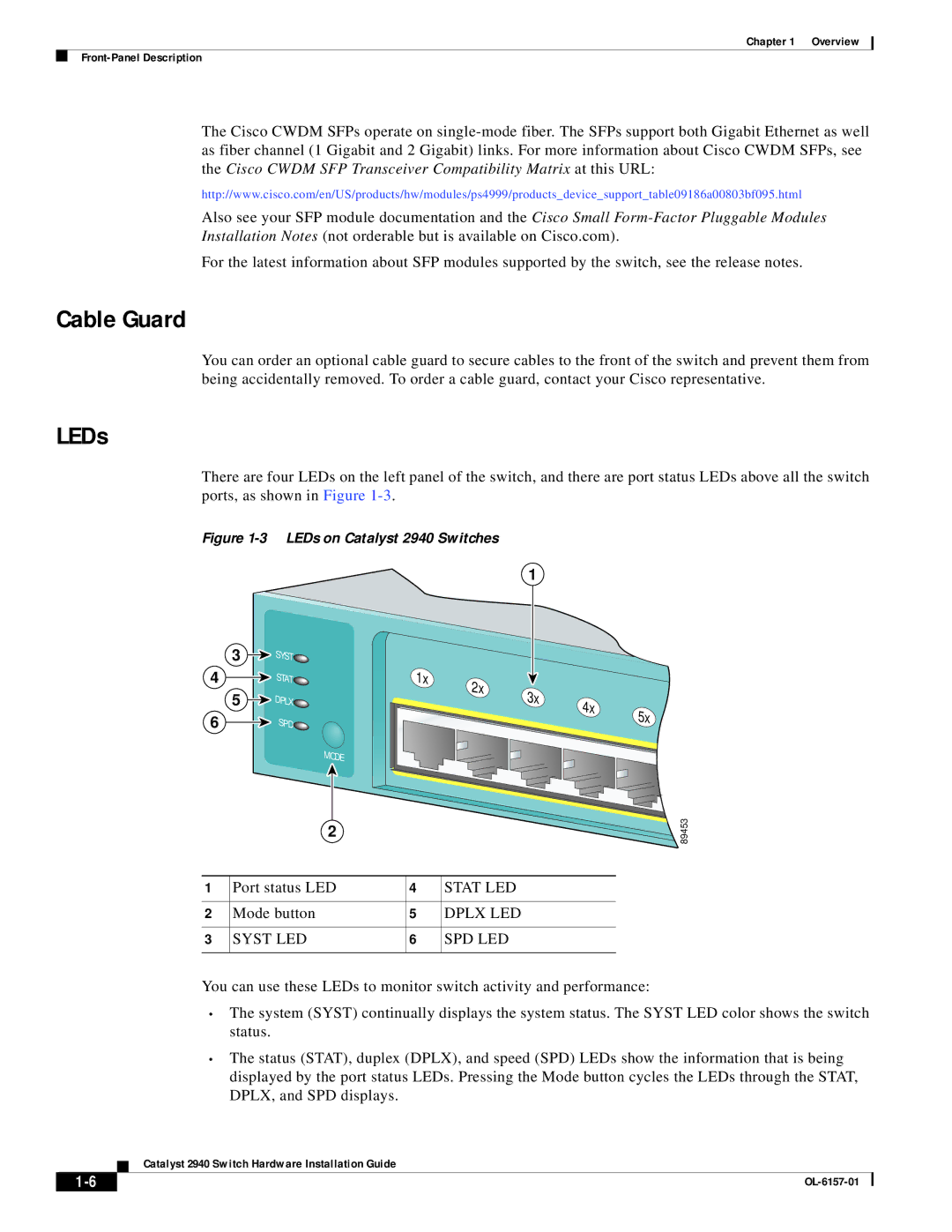
There are four LEDs on the left panel of the switch, and there are port status LEDs above all the switch ports, as shown in Figure
Figure 1-3 LEDs on Catalyst 2940 Switches
1
| 3 | SYST |
|
|
|
|
|
|
4 |
| STAT |
| 1x | 2x |
|
|
|
| 5 | DPLX |
|
| 3x |
|
| |
|
|
|
| 4x |
| |||
|
|
|
|
| 5x | |||
6 |
| SPD |
|
|
|
| ||
|
|
|
|
|
| |||
|
|
|
|
|
|
| ||
|
| MODE |
|
|
|
|
|
|
|
| 2 |
|
|
|
|
|
|
1 | Port status LED | 4 |
| STAT LED |
|
|
| |
2 | Mode button | 5 |
| DPLX LED |
|
|
| |
3 | SYST LED | 6 |
| SPD LED |
|
|
| |
You can use these LEDs to monitor switch activity and performance:
89453
•The system (SYST) continually displays the system status. The SYST LED color shows the switch status.
•The status (STAT), duplex (DPLX), and speed (SPD) LEDs show the information that is being displayed by the port status LEDs. Pressing the Mode button cycles the LEDs through the STAT, DPLX, and SPD displays.
Catalyst 2940 Switch Hardware Installation Guide
| ||
|