Wiring and Signal Assignment Specifications
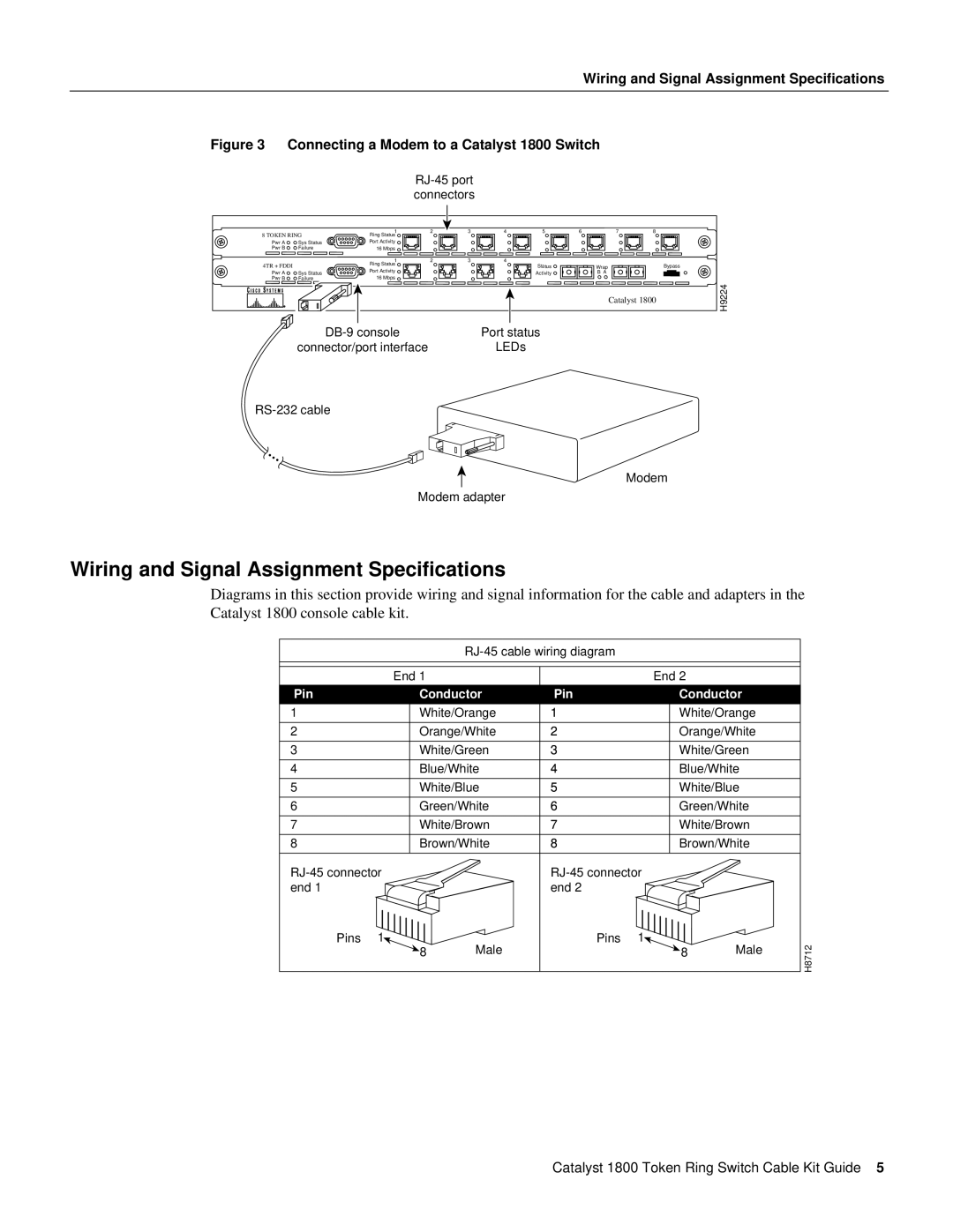
Figure 3 Connecting a Modem to a Catalyst 1800 Switch
RJ-45 port connectors
8 TOKEN RING | 1 | 2 | 3 | 4 | 5 | 6 | 7 | 8 |
| |
Ring Status |
|
|
|
|
|
|
|
| ||
Pwr A | Sys Status | Port Activity |
|
|
|
|
|
|
|
|
Pwr B | Failure | 16 Mbps |
|
|
|
|
|
|
|
|
|
| 1 | 2 | 3 | 4 |
|
|
|
|
|
4TR + FDDI |
| Ring Status |
|
|
| Status | Wrap |
|
| Bypass |
| Port Activity |
|
|
|
|
| ||||
Pwr A | Sys Status |
|
|
| Activity | B A |
|
|
| |
16 Mbps |
|
|
|
|
|
| ||||
Pwr B | Failure |
|
|
|
|
|
|
|
| |
|
|
|
|
|
|
|
| Catalyst 1800 | H9224 | |
|
|
|
|
|
|
|
|
|
| |
Port status | |
connector/port interface | LEDs |
Modem
Modem adapter
Wiring and Signal Assignment Specifications
Diagrams in this section provide wiring and signal information for the cable and adapters in the
Catalyst 1800 console cable kit.
|
|
|
|
| ||
| End 1 |
|
| End 2 |
|
|
Pin | Conductor | Pin | Conductor |
| ||
1 | White/Orange | 1 | White/Orange |
| ||
2 | Orange/White | 2 | Orange/White |
| ||
3 | White/Green | 3 | White/Green |
| ||
4 | Blue/White | 4 | Blue/White |
| ||
5 | White/Blue | 5 | White/Blue |
| ||
6 | Green/White | 6 | Green/White |
| ||
7 | White/Brown | 7 | White/Brown |
| ||
8 | Brown/White | 8 | Brown/White |
| ||
|
|
| ||||
end 1 |
|
| end 2 |
|
|
|
Pins | 1 | Male | Pins | 1 | Male | H8712 |
| 8 |
| 8 | |||
|
|
|
|
|
| |
Catalyst 1800 Token Ring Switch Cable Kit Guide 5