Connecting to a Modem
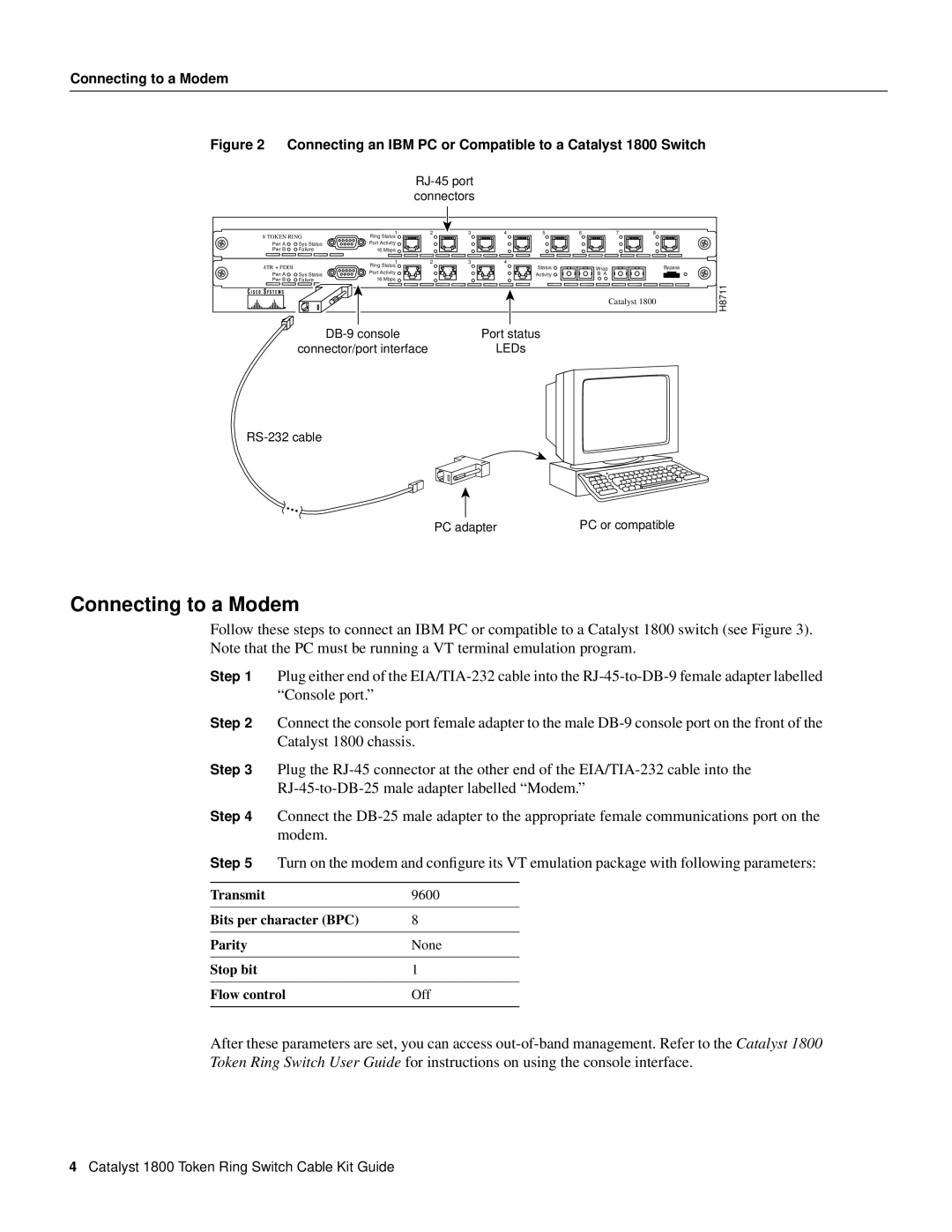
Figure 2 Connecting an IBM PC or Compatible to a Catalyst 1800 Switch
RJ-45 port connectors
8 TOKEN RING | 1 | 2 | 3 | 4 | 5 | 6 | 7 | 8 |
| |
Ring Status |
|
|
|
|
|
|
|
| ||
Pwr A | Sys Status | Port Activity |
|
|
|
|
|
|
|
|
Pwr B | Failure | 16 Mbps |
|
|
|
|
|
|
|
|
|
| 1 | 2 | 3 | 4 |
|
|
|
|
|
4TR + FDDI |
| Ring Status |
|
|
| Status | Wrap |
|
| Bypass |
| Port Activity |
|
|
|
|
| ||||
Pwr A | Sys Status |
|
|
| Activity | B A |
|
|
| |
Pwr B | Failure | 16 Mbps |
|
|
|
|
|
|
| H8711 |
|
|
|
|
|
|
|
| Catalyst 1800 | ||
|
|
|
|
|
|
|
|
|
| |
Port status | |
connector/port interface | LEDs |
PC adapter | PC or compatible |
Connecting to a Modem
Follow these steps to connect an IBM PC or compatible to a Catalyst 1800 switch (see Figure 3). Note that the PC must be running a VT terminal emulation program.
Step 1 Plug either end of the
Step 2 Connect the console port female adapter to the male
Step 3 Plug the
Step 4 Connect the
Step 5 | Turn on the modem and configure its VT emulation package with following parameters: | ||
|
|
|
|
Transmit |
| 9600 |
|
|
|
| |
Bits per character (BPC) | 8 |
| |
|
|
|
|
Parity |
| None | |
|
|
|
|
Stop bit |
| 1 |
|
|
|
| |
Flow control | Off | ||
|
|
|
|
After these parameters are set, you can access
4Catalyst 1800 Token Ring Switch Cable Kit Guide