Chapter 2 Ethernet and Gigabit Ethernet Switching Modules
10/100 and 10/100/1000 Ethernet Switching Modules
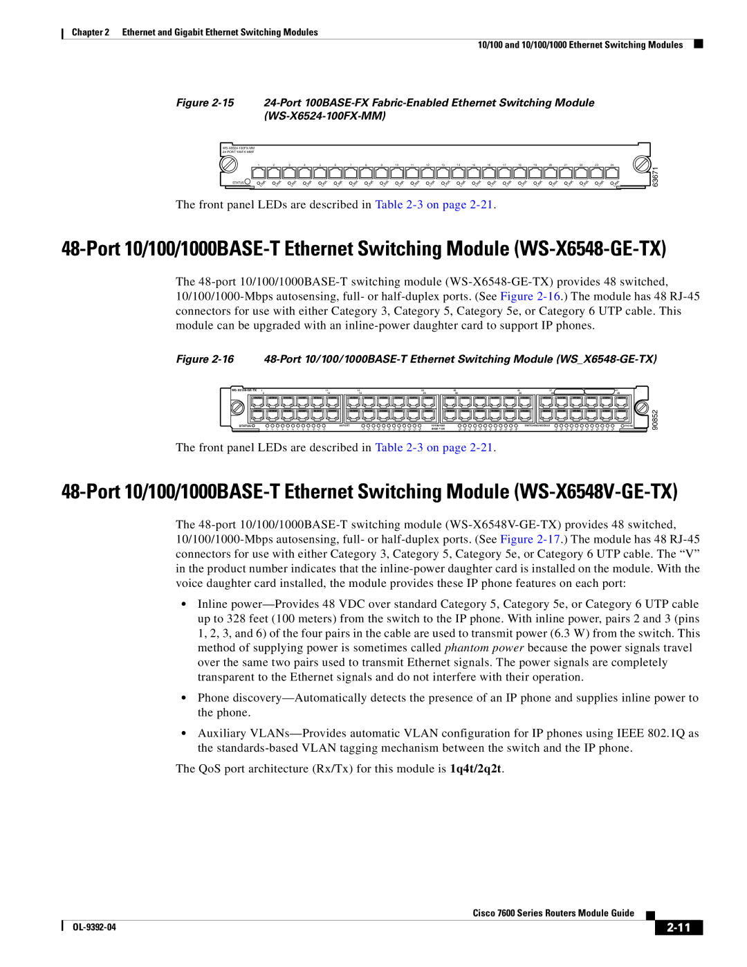
Figure 2-15 24-Port 100BASE-FX Fabric-Enabled Ethernet Switching Module (WS-X6524-100FX-MM)
WS-X6524-100FX-MM 24 PORT 100FX-MMF
| 1 | 2 | 3 | 4 | 5 | 6 | 7 | 8 | 9 | 10 | 11 | 12 | 13 | 14 | 15 | 16 | 17 | 18 | 19 | 20 | 21 | 22 | 23 | | 24 |
STATUS | LINK | LINK | LINK | LINK | LINK | LINK | LINK | LINK | LINK | LINK | LINK | LINK | LINK | LINK | LINK | LINK | | LINK | LINK | LINK | LINK | LINK | LINK | LINK | LINK |
The front panel LEDs are described in Table 2-3 on page 2-21.
63671
48-Port 10/100/1000BASE-T Ethernet Switching Module (WS-X6548-GE-TX)
The 48-port 10/100/1000BASE-T switching module (WS-X6548-GE-TX) provides 48 switched, 10/100/1000-Mbps autosensing, full- or half-duplex ports. (See Figure 2-16.) The module has 48 RJ-45 connectors for use with either Category 3, Category 5, Category 5e, or Category 6 UTP cable. This module can be upgraded with an inline-power daughter card to support IP phones.
Figure 2-16 48-Port 10/100/1000BASE-T Ethernet Switching Module (WS_X6548-GE-TX)
WS-X6148-GE-TX 1 | | | | | | | | | | | 11 |
2 | | | | | | | | | | | 12 |
STATUS | | | | | | | | | | | |
1 | 2 | 3 | 4 | 5 | 6 | 7 | 8 | 9 | 10 | 11 | 12 |
13 | 23 |
14 | 24 |
48 PORT | 10/100/1000 |
13 | 14 | 15 | 16 | 17 | 18 | 19 | 20 | 21 | 22 | 23 | 24 | BASE-T GE |
|
25 | | | | | | | | | | | 35 | 37 | | | | | | | | | | | | | 47 | |
26 | | | | | | | | | | | 36 | 38 | | | | | | | | | | | | | 48 | |
| | | | | | | | | | | | SWITCHING MODULE | | | | | | | | | | | | | PHONE | 90852 |
25 | 26 | 27 | 28 | 29 | 30 | 31 | 32 | 33 | 34 | 35 | 36 | | 37 | 38 | 39 | 40 | 41 | 42 | 43 | 44 | 45 | 46 | 47 | 48 | | |
The front panel LEDs are described in Table 2-3 on page 2-21.
48-Port 10/100/1000BASE-T Ethernet Switching Module (WS-X6548V-GE-TX)
The 48-port 10/100/1000BASE-T switching module (WS-X6548V-GE-TX) provides 48 switched, 10/100/1000-Mbps autosensing, full- or half-duplex ports. (See Figure 2-17.) The module has 48 RJ-45 connectors for use with either Category 3, Category 5, Category 5e, or Category 6 UTP cable. The “V” in the product number indicates that the inline-power daughter card is installed on the module. With the voice daughter card installed, the module provides these IP phone features on each port:
•Inline power—Provides 48 VDC over standard Category 5, Category 5e, or Category 6 UTP cable up to 328 feet (100 meters) from the switch to the IP phone. With inline power, pairs 2 and 3 (pins 1, 2, 3, and 6) of the four pairs in the cable are used to transmit power (6.3 W) from the switch. This method of supplying power is sometimes called phantom power because the power signals travel over the same two pairs used to transmit Ethernet signals. The power signals are completely transparent to the Ethernet signals and do not interfere with their operation.
•Phone discovery—Automatically detects the presence of an IP phone and supplies inline power to the phone.
•Auxiliary VLANs—Provides automatic VLAN configuration for IP phones using IEEE 802.1Q as the standards-based VLAN tagging mechanism between the switch and the IP phone.
The QoS port architecture (Rx/Tx) for this module is 1q4t/2q2t.
Cisco 7600 Series Routers Module Guide