|
|
|
| STEP 5 Power on the devices connected to the Switch. Each active port’s |
3 |
| Installation | ||
|
| Congratulations! The installation of the 10/100 Switch is complete! | ||
|
|
|
| corresponding LED will light up on the Switch. |
|
|
|
| |
Perform the steps in this section to install the hardware. |
|
| ||
|
| |||
|
|
|
|
|
STEP 1 | Make sure all of the devices you will connect to the Switch are |
|
| |
| powered off. |
|
| |
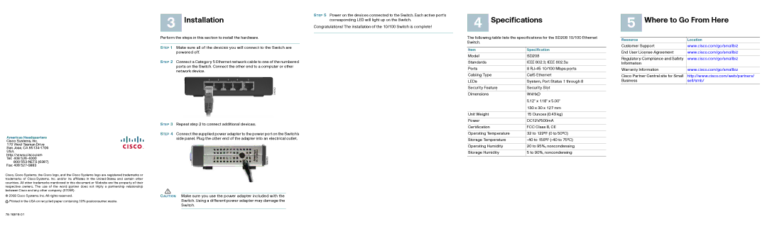
STEP 2 | Connect a Category 5 Ethernet network cable to one of the numbered |
|
| |
| ports on the Switch. Connect the other end to a computer or other |
|
| |
| network device. |
|
| |
4 Specifications
The following table lists the specifications for the SD208 10/100 Ethernet Switch.
Item | Specification |
|
|
Model | SD208 |
|
|
Standards | IEEE 802.3, IEEE 802.3u |
|
|
Ports | 8 |
|
|
Cabling Type | Cat5 Ethernet |
|
|
LEDs | System, Port Status 1 through 8 |
|
|
Security Feature | Security Slot |
|
|
Dimensions | WxHxD |
| 5.12" x 1.18" x 5.00" |
| 130 x 30 x 127 mm |
|
|
Unit Weight | 15 Ounces (0.43 kg) |
|
|
Power | DC12V/500mA |
5 Where to Go From Here
Resource | Location |
|
|
Customer Support | www.cisco.com/go/smallbiz |
|
|
End User License Agreement | www.cisco.com/go/smallbiz |
|
|
Regulatory Compliance and Safety | www.cisco.com/go/smallbiz |
Information |
|
|
|
Warranty Information | www.cisco.com/go/smallbiz |
|
|
Cisco Partner Central site for Small | http://www.cisco.com/web/partners/ |
Business | sell/smb/ |
|
|
Americas Headquarters
Cisco Systems, Inc.
170 West Tasman Drive San Jose, CA
USA http://www.cisco.com Tel: 408
800
Cisco, Cisco Systems, the Cisco logo, and the Cisco Systems logo are registered trademarks or trademarks of Cisco Systems, Inc. and/or its affiliates in the United States and certain other countries. All other trademarks mentioned in this document or Website are the property of their respective owners. The use of the word partner does not imply a partnership relationship between Cisco and any other company. (0705R)
© 2008 Cisco Systems, Inc. All rights reserved.
![]()
![]() Printed in the USA on recycled paper containing 10% postconsumer waste.
Printed in the USA on recycled paper containing 10% postconsumer waste.
STEP 3 Repeat step 2 to connect additional devices.
STEP 4 Connect the supplied power adapter to the power port on the Switch’s side panel. Plug the other end of the adapter into an electrical outlet.
!
CAUTION Make sure you use the power adapter included with the Switch. Using a different power adapter may damage the Switch.
Certification | FCC Class B, CE |
|
|
Operating Temperature | 32 to 122ºF (0 to 50ºC) |
|
|
Storage Temperature | |
|
|
Operating Humidity | 20 to 95%, noncondensing |
|
|
Storage Humidity | 5 to 90%, noncondensing |