Quick Start Guide
Cisco Small Business
Model SD208
Package Contents
•SD208 Switch
•Power Adapter
•Quick Start Guide
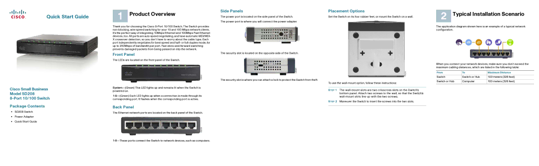
1 Product Overview
Thank you for choosing the Cisco
Front Panel
The LEDs are located on the front panel of the Switch.
Back Panel
The Ethernet network ports are located on the back panel of the Switch.
Side Panels
The power port is located on the side panel of the Switch. The power port is where you will connect the power adapter.
The security slot is located on the opposite side of the Switch.
The security slot is where you can attach a lock to protect the Switch from theft.
Placement Options
Set the Switch on its four rubber feet, or mount the Switch on a wall.
To use the
STEP 1 The
STEP 2 Maneuver the Switch to insert the screws into the two slots.
2 Typical Installation Scenario
The application diagram shown here is an example of a typical network configuration.
When you connect your network devices, make sure you don’t exceed the maximum cabling distances, which are listed in the following table:
From | To | Maximum Distance |
|
|
|
Switch | Switch or Hub | 100 meters (328 feet) |
|
|
|
Switch or Hub | Computer | 100 meters (328 feet) |
|
|
|