Chapter 5

Configuring the Switch

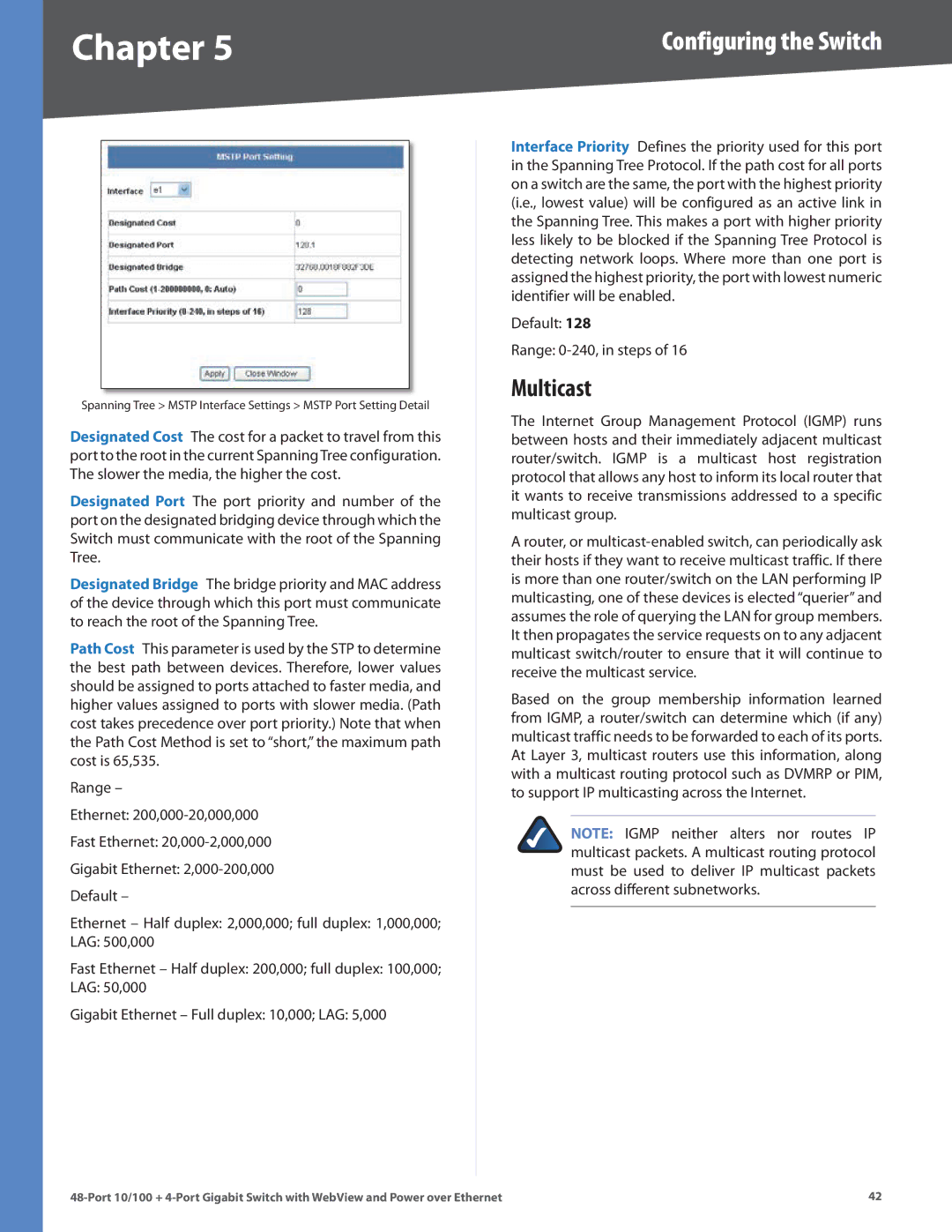
Spanning Tree > MSTP Interface Settings > MSTP Port Setting Detail

Designated Cost  The cost for a packet to travel from this port to the root in the current SpanningTree configuration.. The slower the media, the higher the cost..

Designated Port  The port priority and number of the port on the designated bridging device through which the Switch must communicate with the root of the Spanning Tree..

Designated Bridge  The bridge priority and MAC address of the device through which this port must communicate to reach the root of the Spanning Tree..

Path Cost  This parameter is used by the STP to determine the best path between devices.. Therefore, lower values should be assigned to ports attached to faster media, and higher values assigned to ports with slower media.. (Path cost takes precedence over port priority..) Note that when the Path Cost Method is set to “short,” the maximum path cost is 65,535..

Range –

Ethernet: 200,000-20,000,000

Fast Ethernet: 20,000-2,000,000

Gigabit Ethernet: 2,000-200,000 Default –

Ethernet – Half duplex: 2,000,000; full duplex: 1,000,000;

LAG: 500,000

Fast Ethernet – Half duplex: 200,000; full duplex: 100,000;

LAG: 50,000

Gigabit Ethernet – Full duplex: 10,000; LAG: 5,000

Interface Priority  Defines the priority used for this port in the Spanning Tree Protocol.. If the path cost for all ports on a switch are the same, the port with the highest priority (i..e.., lowest value) will be configured as an active link in the Spanning Tree.. This makes a port with higher priority less likely to be blocked if the Spanning Tree Protocol is detecting network loops.. Where more than one port is assigned the highest priority, the port with lowest numeric identifier will be enabled..

Default: 128

Range: 0-240, in steps of 16

Multicast

The Internet Group Management Protocol (IGMP) runs between hosts and their immediately adjacent multicast router/switch.. IGMP is a multicast host registration protocol that allows any host to inform its local router that it wants to receive transmissions addressed to a specific multicast group..

A router, or multicast-enabled switch, can periodically ask their hosts if they want to receive multicast traffic.. If there is more than one router/switch on the LAN performing IP multicasting, one of these devices is elected “querier” and assumes the role of querying the LAN for group members.. It then propagates the service requests on to any adjacent multicast switch/router to ensure that it will continue to receive the multicast service..

Based on the group membership information learned from IGMP, a router/switch can determine which (if any) multicast traffic needs to be forwarded to each of its ports.. At Layer 3, multicast routers use this information, along with a multicast routing protocol such as DVMRP or PIM, to support IP multicasting across the Internet..

NOTE: IGMP neither alters nor routes IP multicast packets.. A multicast routing protocol must be used to deliver IP multicast packets across different subnetworks..

48-Port 10/100 + 4-Port Gigabit Switch with WebView and Power over Ethernet

42

Page 46
Image 46
Cisco Systems SRW248G4P manual Multicast

SRW248G4P specifications

Cisco Systems SRW248G4P is a high-performance Layer 2 switch designed specifically for small to medium-sized businesses that require robust networking solutions. This switch supports Power over Ethernet (PoE), providing a highly flexible option for powering devices such as IP phones, wireless access points, and surveillance cameras.

One of the standout features of the SRW248G4P is its 48 10/100 Ethernet ports, which ensure ample connectivity for various networked devices. Additionally, it offers four Gigabit Ethernet uplink ports, allowing for seamless integration with existing network infrastructure and facilitating high-speed data transfer. The combination of these ports enables businesses to expand their network capabilities as needed without the immediate requirement for added devices.

The SRW248G4P comes equipped with advanced Layer 2 switching capabilities, including VLAN support, which enables the segmentation of network traffic for improved performance and security. It also supports Spanning Tree Protocol (STP) and Rapid Spanning Tree Protocol (RSTP), which help prevent network loops and ensure redundancy. With features like Link Aggregation Control Protocol (LACP), multiple physical connections can be combined into a single logical link, enhancing bandwidth and providing failover capabilities.

Another critical attribute of the Cisco SRW248G4P is its user-friendly management interface. The switch can be managed through a web-based interface, allowing IT administrators to configure settings, monitor performance, and troubleshoot issues with ease. Additionally, it supports SNMP (Simple Network Management Protocol) for integration with network management systems, further simplifying monitoring tasks.

Power over Ethernet functionality is a significant advantage of the SRW248G4P, providing up to 15.4 watts per port. This capability simplifies installation and reduces the clutter of power cords and outlets. Organizations can deploy PoE-enabled devices in locations that lack power sources, thus enhancing overall flexibility in network design.

In summary, the Cisco Systems SRW248G4P is a feature-rich switch tailored for small to medium-sized enterprises. Its blend of performance, management capabilities, and advanced features like PoE makes it a valuable asset in any organization's networking setup. By ensuring reliable connectivity and ease of management, businesses can focus more on growth and their core objectives rather than worrying about network complexities.