
APX201.2, APX401.2 specifications
The Clarion APX401.2 and APX201.2 are high-performance amplifiers designed to enhance the audio experience in vehicles, providing powerful sound and impressive clarity. These models boast advanced technologies and features that make them a popular choice among car audio enthusiasts.One of the standout features of both the APX401.2 and the APX201.2 is their Class D amplifier topology. This technology allows for efficient power consumption, reduced heat generation, and a compact form factor, making these amplifiers ideal for modern vehicles with limited space. The Class D design provides high output power, ensuring that users can enjoy their music at high volumes without distortion.
The APX401.2 is a four-channel amplifier capable of delivering a maximum power output of 400 watts. This model is suitable for powering a full-range speaker system, allowing users to drive multiple speakers while maintaining sound quality. The built-in low-pass filter and high-pass filter options enable customization of sound frequencies, ensuring that the audio output is tailored to the listener's preferences and the speakers' capabilities.
On the other hand, the APX201.2 is a two-channel amplifier that provides up to 200 watts of maximum power. This model is perfect for those who want to power a pair of speakers or a subwoofer with precision and clarity. The APX201.2 also includes adjustable gain control, allowing users to optimize the input signal to achieve the best possible sound.
Both amplifiers feature a reinforced aluminum chassis that enhances durability and protects against vibrations, which are common in a mobile environment. The aesthetic design, characterized by a sleek and modern finish, ensures that these amplifiers can blend seamlessly with most car interiors.
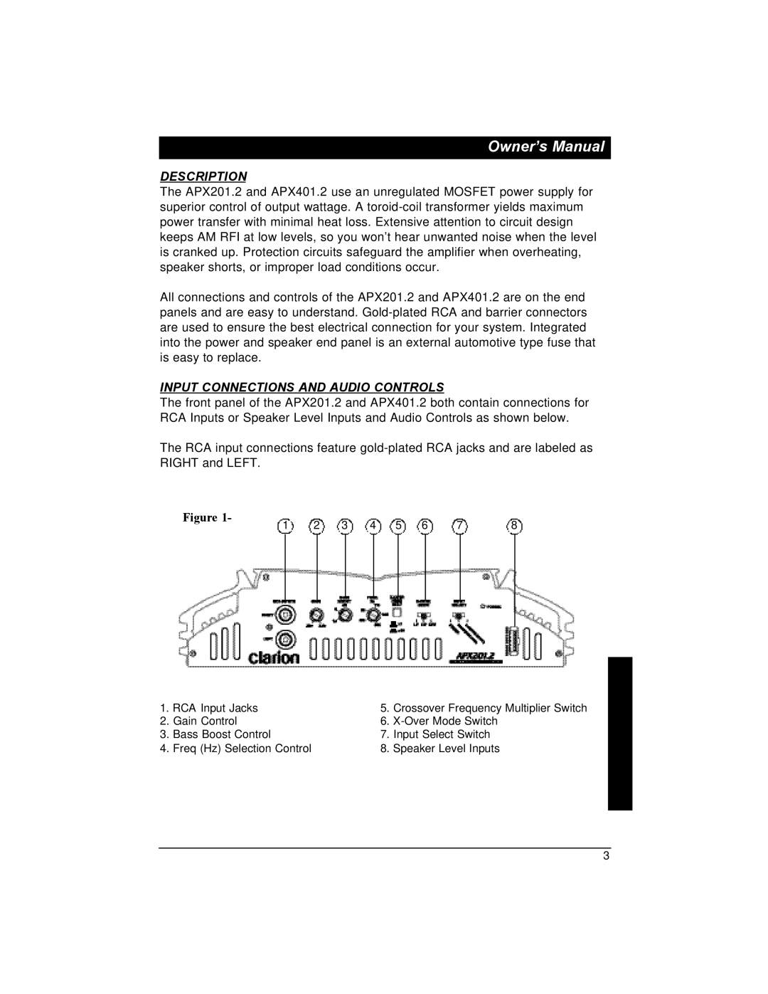
In terms of connectivity, the APX401.2 and APX201.2 come equipped with RCA inputs, allowing for easy integration with aftermarket head units. Moreover, the amplifiers feature a compact design, making installation straightforward and accommodating in various vehicle types.
Finally, these amplifiers are engineered with a range of safety features, including short circuit protection, thermal protection, and overload protection. These safeguards ensure reliable operation, giving users peace of mind while enjoying their audio experience.
In summary, the Clarion APX401.2 and APX201.2 amplifiers offer high-quality sound output, advanced features, and a durable design, making them exceptional choices for anyone looking to elevate their vehicle's audio system. Whether powering multiple speakers or a dedicated subwoofer, these amplifiers deliver performance and reliability, ensuring an enjoyable listening experience on the road.