LOCATION OF CONTROLS
1
3
2
4
5 ![]()
![]()
![]()
![]()
![]() 6
6 ![]()
![]()
![]()
![]() 7
7 ![]()
![]()
![]() 8
8 ![]()
![]()
![]() 9
9
10
POWER SUPPLY AND CONNECTION
Battery Operation
–Remove the battery compartment cover.
–Insert 8 x "C" batteries
–Replace the cover.
Note: Check your batteries regularly, old or dead batteries should be replaced. If the unit is not going to be used for a long time or is being run exclusively on AC power, remove the batteries to avoid leakage and damage.
|
|
| 11 | 12 | 13 14 15 16 17 18 19 | |
21 | 22 | 23 | 24 |
| 21 | 25 |
20 |
|
26 | 27 |
To remove batteries from the compartment, open the cover and simply shake the unit gently.
AC Operation
Take the supplied AC power cord and connect the corresponding ends to the AC socket and the household outlet. Make sure the voltage is compatible.
Note: If | you unplug the AC power cord from the AC socket |
or | from the unit, the unit will operate from DC power. |
RADIO OPERATION
|
|
|
| 28 |
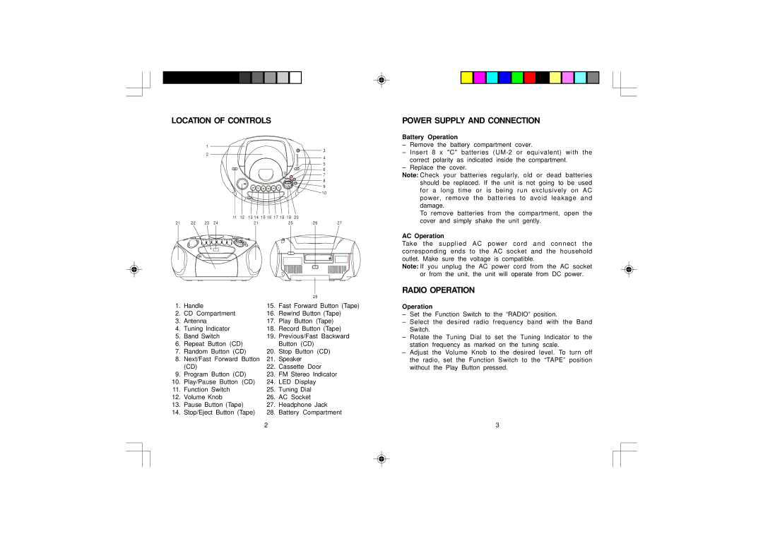
1. | Handle |
| 15. | Fast Forward Button (Tape) |
2. | CD Compartment |
| 16. | Rewind Button (Tape) |
3. | Antenna |
| 17. | Play Button (Tape) |
4. | Tuning Indicator |
| 18. | Record Button (Tape) |
5. | Band Switch |
| 19. | Previous/Fast Backward |
6. | Repeat Button (CD) |
| Button (CD) | |
7. | Random Button (CD) | 20. | Stop Button (CD) | |
8. | Next/Fast Forward | Button | 21. | Speaker |
| (CD) |
| 22. | Cassette Door |
9. | Program Button (CD) | 23. | FM Stereo Indicator | |
10. | Play/Pause Button | (CD) | 24. | LED Display |
11. | Function Switch |
| 25. | Tuning Dial |
12. | Volume Knob |
| 26. | AC Socket |
13. | Pause Button (Tape) | 27. | Headphone Jack | |
14. | Stop/Eject Button (Tape) | 28. | Battery Compartment | |
|
|
| 2 |
|
Operation
–Set the Function Switch to the “RADIO” position.
–Select the desired radio frequency band with the Band Switch.
–Rotate the Tuning Dial to set the Tuning Indicator to the station frequency as marked on the tuning scale.
–Adjust the Volume Knob to the desired level. To turn off the radio, set the Function Switch to the “TAPE” position without the Play Button pressed.
3