AC Power and Control
AC Power Input 
Your RCD-1072 is configured at the factory for the proper AC voltage in the country where you purchased it (either 115 volts or 230/ 240 volts. The AC line configuration is noted on a decal on the back panel.
Note: Should you move your CD player to another country, it may be possible to reconfigure it for use on a different line voltage. Do not attempt to perform this con- version yourself. Opening the enclosure of the RCD-1072 exposes you to dangerous voltages. Consult a qualified service person or the Rotel factory service department for information.
The RCD-1072 should be plugged directly into a 2-pin polarized wall outlet or into the switched outlet on another component in your audio system. Do not use an extension cord.
Be sure the power switch on the front panel of the RCD-1072 is turned off (in the “out” position). Then, connect the supplied power cord to the AC power receptacle on the rear of the unit and the AC power outlet.
If you are going to be away from home for an extended period of time such as a month-long vacation, it is a sensible precaution to unplug your CD player (as well as other audio and video components) while you are away.
Power Switch  and Power Indicator
The power switch is located on the front panel of your CD player. To turn the CD player on, push the switch in. The LED indicator above the switch and the Display will light up, indicating that the CD player is turned on. To turn the CD player off, push the button again and return it to the “out” position.
Note: If you are using a switched outlet to turn on and off your CD player, you should leave the power switch in the “on” position. When AC power is applied to the unit, it will power up in fully active mode.
Output Connections
The RCD-1072 gives you a choice of two different kinds of outputs – an analog output signal from the built-in D/A converter for use with conventional analog audio components and a coax digital output which provides an unprocessed digital signal for use with outboard D/A converters or digital processors.
Note: To prevent loud noises that could damage your speakers, turn off all the sys- tem components when you make any signal connections.
Analog Outputs 
[See Figure 3 for wiring illustration]
A pair of standard RCA jacks supplies an analog output signal from the RCD-1072 to the source inputs of an audio preamplifier, in-tegrated amplifier, or receiver.
Select high quality audio interconnect cables. Connect the left and right channel outputs of the RCD-1072 to the corresponding inputs on the preamplifier or other component.
Digital Output 
[See Figure 4 for wiring illustration]
If you are using an outboard D/A converter or other digital processor, you will need an unprocessed digital data stream from the RCD-1072. Using a standard 75 ohm coax digital cable, connect the RCD-1072’s digital output to the digital input connector on the outboard D/A converter.
12 Volt Trigger Input 
The RCD-1072 can be activated by a 12 volt trigger signal. The trigger input accepts any control signal (AC or DC) ranging from 3 volts to 30 volts. When a cable is connected to the 12V input and a trigger signal is present, the RCD-1072 is activated. When the trigger signal is turned off, the unit goes into standby mode. The front panel power indicator remains lit, but the display goes dark and the unit will not operate.
NOTE: When using the 12V Trigger feature, leave the POWER button in the ON position.
EXT REMOTE IN Jack 
This 3.5mm mini-jack receives command codes from industry-standard infrared receivers (Xantech, etc.) via hard-wired connections. This feature could prove useful when the unit is installed in a cabinet and the front-panel sensor is blocked. Consult your authorized Rotel dealer for information on these external repeaters and the proper wiring of a jack to fit the mini-jack receptacle.
Operation
The RCD-1072 can be operated using its front panel buttons or from corresponding buttons on the supplied infrared remote control. Spe- cific instructions for each of these controls are detailed below. Most of the buttons are dupli- cated on the front panel and on the IR remote control. However, there are a few exceptions where the buttons are only available on one or the other. These exceptions are noted in the instructions.
Infrared Remote Control 
Before using the IR remote control, it is neces- sary to install two “UM-4/AAA” batteries (supplied). Remove the plastic cover on the back of the IR remote, install the batteries (observing the + and – polarity indications), and reinstall the cover.
To use the IR remote control, aim it at the IR
sensor  located in the lower left corner of the RCD-1072 front panel.
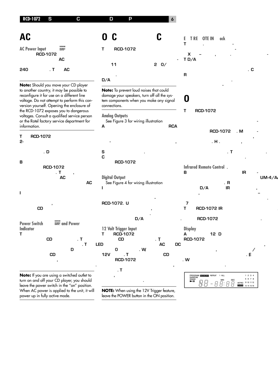
Display 
A lighted Display on the front panel of the RCD-1072 provides useful information about the status of the unit, activation of special features, and track/time information for the disc being played. Each of these indicators is described in the detailed operating instructions that follow.


 and Power Indicator


![]() located in the lower left corner of the
located in the lower left corner of the 
