Assembly cont.
Step 1 (cont)
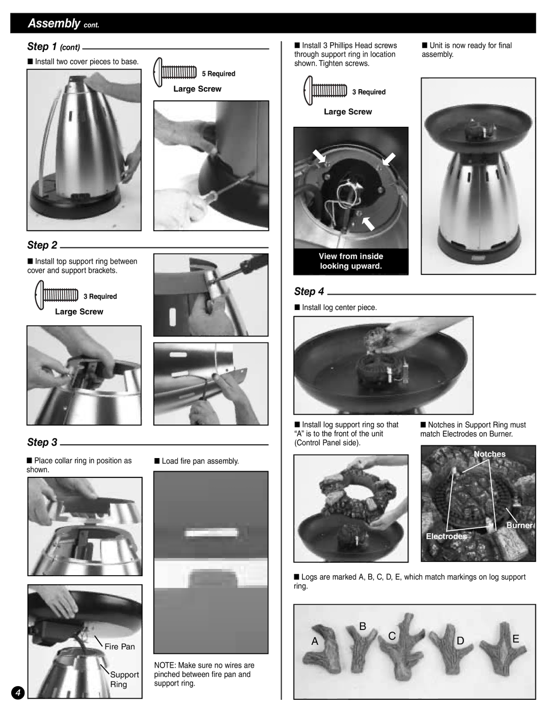
■Install two cover pieces to base.
5 Required
Large Screw
Step 2
■Install top support ring between cover and support brackets.
3 Required
Large Screw
Step 3
■ Place collar ring in position as |
| ■ Load fire pan assembly. | |
shown. |
|
| |
|
| ||
|
|
|
|
|
|
|
|
Fire Pan |
|
| NOTE: Make sure no wires are |
Support | pinched between fire pan and |
Ring | support ring. |
4
■ Install 3 Phillips Head screws | ■ Unit is now ready for final |
through support ring in location | assembly. |
shown. Tighten screws. |
|
3 Required
Large Screw
View from inside looking upward.
Step 4
■Install log center piece.
■ Install log support ring so that | ■ Notches in Support Ring must | |
“A” is to the front of the unit | match Electrodes on Burner. | |
(Control Panel side). |
|
|
|
| Notches |
| ||
Burner
Electrodes
■Logs are marked A, B, C, D, E, which match markings on log support ring.
B
ACDE