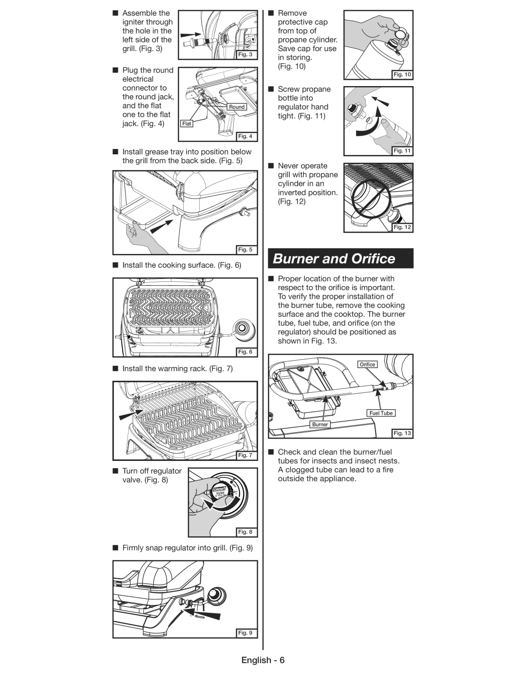
■ Assemble the |
| ■ Remove |
igniter through |
| protective cap |
the hole in the |
| from top of |
left side of the |
| propane cylinder. |
grill. (Fig. 3) | Fig. 3 | Save cap for use |
| in storing. | |
|
| |
■ Plug the round |
| (Fig. 10) |
| Fig. 10 | |
electrical |
| |
|
| |
connector to |
| ■ Screw propane |
the round jack, |
| bottle into |
and the flat | Round | regulator hand |
one to the flat |
| tight. (Fig. 11) |
jack. (Fig. 4) | Flat |
|
| Fig. 4 |
|
■ Install grease tray into position below | Fig. 11 | |
the grill from the back side. (Fig. 5) | ■ Never operate | |
|
| |
|
| grill with propane |
|
| cylinder in an |
|
| inverted position. |
|
| (Fig. 12) |
Fig. 12 |
|
| Fig. 5 | Burner and Orifice | |
■ Install the cooking surface. (Fig. 6) | ||||
| ||||
|
|
| ■ Proper location of the burner with | |
|
|
| respect to the orifice is important. | |
|
|
| To verify the proper installation of | |
|
|
| the burner tube, remove the cooking | |
|
|
| surface and the cooktop. The burner | |
|
|
| tube, fuel tube, and orifice (on the | |
|
|
| regulator) should be positioned as | |
|
|
| shown in Fig. 13. | |
|
| Fig. 6 |
| |
■ Install the warming rack. (Fig. 7) | Orifice | |||
| ||||
|
|
| Fuel Tube | |
|
|
| Burner | |
|
|
| Fig. 13 | |
|
| Fig. 7 | ■ Check and clean the burner/fuel | |
|
| tubes for insects and insect nests. | ||
|
|
| ||
■ Turn off regulator |
|
| A clogged tube can lead to a fire | |
valve. (Fig. 8) |
|
| outside the appliance. | |
|
| OFF |
| |
HIGH |
|
|
| |
PUSH | LOW |
| ||
& Off |
| |||
to Turn | On |
|
| |
|
|
| ||
|
| Fig. 8 |
| |
■Firmly snap regulator into grill. (Fig. 9)
Fig. 9 |
English - 6 |
