S Q U A R E S T R A I G H T S T E E L P O L E S
O R D E R I N G I N F O R M AT I O N
S A M P L E N U M B E R : S S S 5 A 2 0 S F M 1 X G
|
|
|
|
|
|
| Mounting |
|
|
| Fixture |
| No. & |
|
|
| Accessories | |
|
|
| Shaft 3 |
| Wall |
| Height | Base |
|
| Mounting |
| Location | Arm | (Ground | |||
Square | Straight | Steel | Size |
| Thickness | (ft.) | Type | Finish | & Type |
| of Arms |
| Lengths | Lug) | ||||
S | S | S | 5 |
| A |
| 20 | S | F |
| M |
|
| 1 |
| X |
| G |
|
|
|
| Bolt |
|
| Anchor |
|
|
|
|
|
|
|
|
|
|
|
|
|
| Base | Circle | Bolt | Shaft | Bolt |
| Net. |
|
|
|
|
|
|
|
| Max. Fixture |
Mtg. | Catalog 1, 2 | Wall | Square | Dia. | Proj. | Size | Dia. &. |
| Wt. | EPA (Sq. Ft.) 4 |
| EPA (Sq. Ft.) 4 |
| |||||
Height | Number | Thickness | (In.) | (In.) | (In.) | (In.) | Length (In.) |
| (Lbs.) | At Pole Top |
|
| 2' Above Pole Top | Bracket (Lbs.) | ||||
MH |
|
| S | BC | BP | B | AB |
|
| 70 | 80 | 90 | 100 | 70 | 80 | 90 | 100 |
|
10 | SSS4A10SF | .120 | 10 1/2 | 11.0 | 4 1/2 | 4 | 3/4 x 25 x 3 |
| 96 | 39.8 | 29.9 | 23.2 | 18.4 | 33.0 | 24.8 | 19.3 | 15.3 | 150 |
15 | SSS4A15SF | .120 | 10 1/2 | 11.0 | 4 1/2 | 4 | 3/4 x 25 x 3 |
| 133 | 19.6 | 14.4 | 10.8 | 8.2 | 17.2 | 12.7 | 9.5 | 7.3 | 150 |
20 | SSS4A20SF | .120 | 10 1/2 | 11.0 | 4 1/2 | 4 | 3/4 x 25 x 3 |
| 152 | 12.9 | 9.1 | 6.5 | 4.6 | 11.7 | 8.2 | 5.9 | 4.2 | 200 |
25 | SSS4A25SF | .120 | 10 1/2 | 11.0 | 4 1/2 | 4 | 3/4 x 25 x 3 |
| 208 | 8.7 | 5.6 | 3.6 | 2.1 | 8.0 | 5.2 | 3.3 | 2.0 | 200 |
20 | SSS5A20SF | .120 | 10 1/2 | 11.0 | 4 1/2 | 5 | 3/4 x 25 x 3 |
| 202 | 21.9 | 15.7 | 11.6 | 8.5 | 19.9 | 14.3 | 10.5 | 7.7 | 200 |
25 | SSS5A25SF | .120 | 10 1/2 | 11.0 | 4 1/2 | 5 | 3/4 x 25 x 3 |
| 248 | 15.5 | 10.5 | 7.2 | 4.8 | 14.3 | 9.8 | 6.6 | 4.4 | 200 |
30 | SSS5A30SF | .120 | 10 1/2 | 11.0 | 4 1/2 | 5 | 3/4 x 25 x 3 |
| 293 | 8.2 | 4.6 | 2.1 | 7.7 | 4.3 | 2.0 | 300 | ||
35 | SSS5M35SF | .188 | 10 1/2 | 11.0 | 4 1/2 | 5 | 3/4 x 25 x 3 |
| 480 | 11.8 | 7.1 | 3.8 | 1.5 | 11.1 | 6.6 | 3.6 | 1.4 | 300 |
25 | SSS6A25SF | .120 | 12 1/2 | 12.5 | 5 | 6 | 1 x 36 x 4 |
| 295 | 24.1 | 16.8 | 12.0 | 8.5 | 22.2 | 15.6 | 11.1 | 7.8 | 200 |
30 | SSS6A30SF | .120 | 12 1/2 | 12.5 | 5 | 6 | 1 x 36 x 4 |
| 347 | 14.0 | 8.7 | 5.0 | 2.5 | 13.1 | 8.2 | 4.7 | 2.3 | 300 |
30 | SSS6M30SF | .188 | 12 1/2 | 12.5 | 5 | 6 | 1 x 36 x 4 |
| 505 | 26.4 | 18.1 | 12.5 | 8.4 | 24.7 | 16.9 | 11.6 | 7.9 | 300 |
35 | SSS6M35SF | .188 | 12 1/2 | 12.5 | 5 | 6 | 1 x 36 x 4 |
| 584 | 19.7 | 12.7 | 7.9 | 4.4 | 18.6 | 12.0 | 7.5 | 4.2 | 300 |
35 | SSS6X35SF | .250 | 12 1/2 | 12.5 | 5 | 6 | 1 x 36 x 4 |
| 696 | 28.9 | 19.7 | 13.4 | 8.9 | 8.7 | 18.6 | 12.7 | 8.4 | 300 |
39 | SSS6M39SF | .188 | 12 1/2 | 12.5 | 5 | 6 | 1 x 36 x 4 |
| 647 | 15.4 | 9.1 | 4.8 | 1.8 | 14.6 | 8.7 | 4.6 | 1.7 | 300 |
39 | SSS6X39SF | .250 | 12 1/2 | 12.5 | 5 | 6 | 1 x 36 x 4 |
| 822 | 23.5 | 15.4 | 9.8 | 5.7 | 22.4 | 14.6 | 9.3 | 5.4 | 300 |
NOTES: 1 Catalog number includes pole with anchor bolts with double nuts (BEFORE INSTALLING ANCHOR BOLTS MAKE SURE PROPER ANCHOR BOLT TEMPLATE IS OBTAINED FROM COOPER LIGHTING). |
|
|
|
| ||||||||||||||
2 Tenon size or machining for rectangular arms must be specified. Hand hole is located 180° from single arm. |
|
|
|
|
|
|
|
|
|
|
| |||||||
3 Shaft size, base plate, anchor bolts and projections may vary |
|
|
|
|
|
|
|
|
|
|
|
| ||||||
4 EPA’s based on shaft properties with wind normal to flat. EPA’s calculated using base wind velocity as indicated plus 30% gust factor. |
|
|
|
|
|
|
|
|
|
| ||||||||
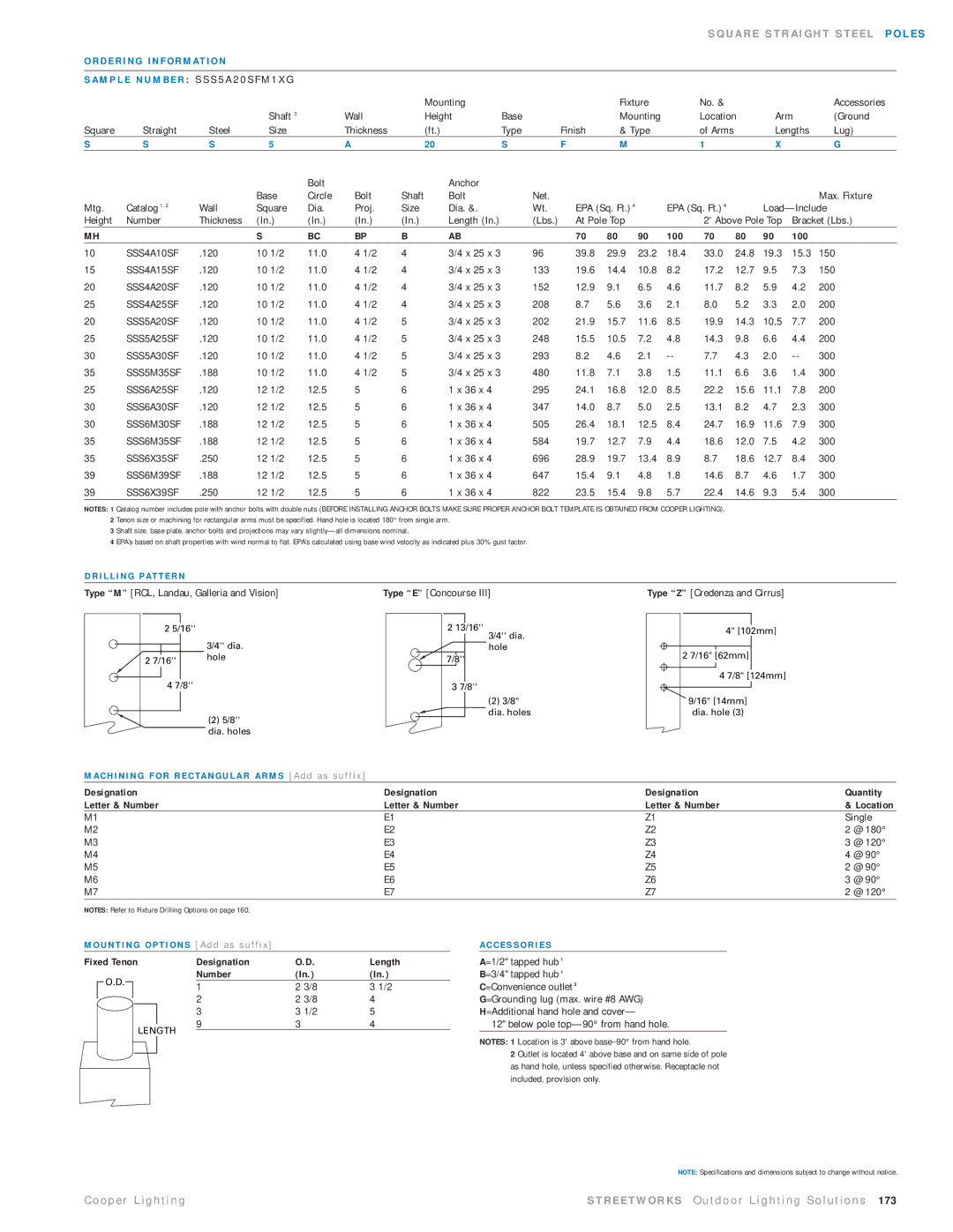
D R I L L I N G PAT T E R N |
|
|
|
|
|
|
|
|
|
|
|
|
|
|
|
|
| |
Type “M” [RCL, Landau, Galleria and Vision] |
|
| Type “E” [Concourse III] |
|
|
|
| Type “Z” [Credenza and Cirrus] |
|
| ||||||||
2 5/16'' |
| 2 13/16'' |
| 3/4'' dia. |
|
2 7/16'' | hole | 7/8'' |
4 7/8'' |
| 3 7/8'' |
3/4'' dia. | 4" [102mm] | |
|
| |
hole |
|
|
2 7/16" [62mm] |
| |
|
| |
|
|
|
| 4 7/8" [124mm] | |
|
|
|
(2)5/8'' dia. holes
(2) 3/8" | 9/16" [14mm] |
dia. holes | dia. hole (3) |
M A C H I N I N G F O R R E C TA N G U L A R A R M S [ A d d a s s u f f i x ]
Designation | Designation | Designation | Quantity | |
Letter & Number | Letter & Number | Letter & Number | & Location | |
M1 | E1 | Z1 | Single | |
M2 | E2 | Z2 | 2 | @ 180° |
M3 | E3 | Z3 | 3 | @ 120° |
M4 | E4 | Z4 | 4 | @ 90° |
M5 | E5 | Z5 | 2 | @ 90° |
M6 | E6 | Z6 | 3 | @ 90° |
M7 | E7 | Z7 | 2 | @ 120° |
NOTES: Refer to Fixture Drilling Options on page 160.
M O U N T I N G O P T I O N S [ A d d a s s u f f i x ] |
|
|
| A C C E S S O R I E S | ||||||||
Fixed Tenon |
|
| Designation | O.D. | Length | A=1/2" tapped hub 1 | ||||||
|
| O.D. |
|
|
|
|
| Number | (In.) | (In.) | B=3/4" tapped hub 1 | |
|
|
|
|
|
|
| 1 | 2 3/8 | 3 1/2 |
| C=Convenience outlet 2 | |
|
|
|
|
|
|
|
| |||||
|
|
|
|
| 2 | 2 3/8 | 4 |
| G=Grounding lug (max. wire #8 AWG) | |||
|
|
|
|
|
| |||||||
|
|
|
|
|
|
| 3 | 3 1/2 | 5 |
| H=Additional hand hole and cover— | |
|
|
|
|
|
|
| 9 | 3 | 4 |
| 12" below pole | |
|
|
|
|
|
|
| ||||||
|
|
|
|
| LENGTH |
|
|
|
|
| ||
|
|
|
|
|
|
|
|
| ||||
NOTES: 1 Location is 3' above
2 Outlet is located 4' above base and on same side of pole as hand hole, unless specified otherwise. Receptacle not included, provision only.
NOTE: Specifications and dimensions subject to change without notice.
C o o p e r L i g h t i n g | S T R E E T W O R K S O u t d o o r L i g h t i n g S o l u t i o n s 173 |