
VS Series specifications
Cooper Lighting's VS Series represents a significant advancement in the field of indoor and outdoor lighting solutions. Designed for versatility and efficiency, the VS Series provides a wide array of features that cater to various applications, ensuring optimal illumination and performance.One of the standout characteristics of the VS Series is its energy efficiency. Utilizing LED technology, these fixtures consume significantly less energy compared to traditional lighting systems. This not only reduces energy costs for users but also contributes to a more sustainable environment. Additionally, the long lifespan of LED lights means less frequent replacements, further enhancing cost-effectiveness and reliability.
The VS Series is built with durability in mind, featuring robust construction that withstands harsh conditions. This makes it suitable for both commercial and industrial environments, where durability is essential for maintaining continuous operations. The fixtures come with a range of IP ratings, ensuring protection against dust and moisture, which is critical for outdoor applications or areas exposed to challenging conditions.
A key highlight of the VS Series is its advanced optical technology. The fixtures are designed to provide uniform lighting distribution, minimizing dark spots and ensuring even illumination across the desired area. This feature is particularly valuable in environments where safety and visibility are paramount, such as parking lots, roadways, and public spaces.
Furthermore, the VS Series offers exceptional flexibility in terms of control options. Users can choose from various dimming and smart control features, allowing for tailored lighting solutions that adapt to changing needs throughout the day. Integration with building management systems is seamless, enabling users to monitor and optimize energy usage effectively.
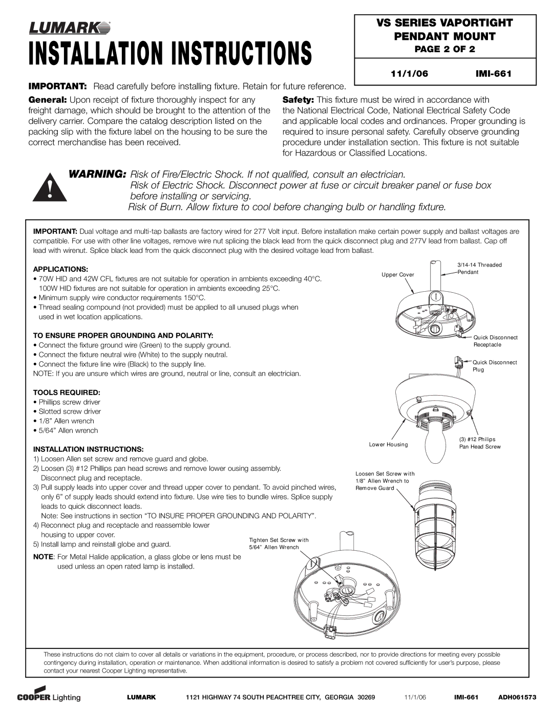
Installation of VS Series fixtures is straightforward, thanks in part to their modular design. This simplifies maintenance and reduces downtime, making it an ideal choice for busy environments where operational efficiency is crucial.
In summary, the Cooper Lighting VS Series stands out for its energy efficiency, durability, advanced optical performance, and flexible control options. These features make it a premier choice for both indoor and outdoor applications, reaffirming Cooper Lighting's commitment to providing innovative solutions in the lighting industry. Whether for commercial, industrial, or residential use, the VS Series is designed to meet the diverse demands of modern lighting needs while promoting sustainability and efficiency.