NOTE: Only qualified personnel should install this kit.
1. Unpack
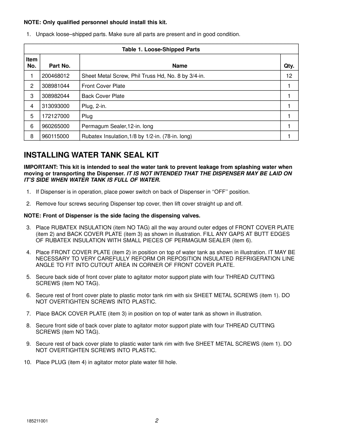
Table 1. Loose-Shipped Parts
Item |
|
|
|
No. | Part No. | Name | Qty. |
|
|
|
|
1 | 200468012 | Sheet Metal Screw, Phil Truss Hd, No. 8 by | 12 |
|
|
|
|
2 | 308981044 | Front Cover Plate | 1 |
|
|
|
|
3 | 308982044 | Back Cover Plate | 1 |
|
|
|
|
4 | 313093000 | Plug, | 1 |
|
|
|
|
5 | 172127000 | Plug | 1 |
|
|
|
|
6 | 960265000 | Permagum | 1 |
|
|
|
|
8 | 960115000 | Rubatex Insulation,1/8 by | 1 |
|
|
|
|
INSTALLING WATER TANK SEAL KIT
IMPORTANT: This kit is intended to seal the water tank to prevent leakage from splashing water when moving or transporting the Dispenser. IT IS NOT INTENDED THAT THE DISPENSER MAY BE LAID ON IT’S SIDE WHEN WATER TANK IS FULL OF WATER.
1.If Dispenser is in operation, place power switch on back of Dispenser in ‘‘OFF’’ position.
2.Remove four screws securing Dispenser top cover, then lift cover straight up and off.
NOTE: Front of Dispenser is the side facing the dispensing valves.
3.Place RUBATEX INSULATION (item NO TAG) all the way around outer edges of FRONT COVER PLATE (item 2) and BACK COVER PLATE (item 3) as shown in illustration. FILL ANY GAPS AT BUTT EDGES OF RUBATEX INSULATION WITH SMALL PIECES OF PERMAGUM SEALER (item 6).
4.Place FRONT COVER PLATE (item 2) in position on top of water tank as shown in illustration. IT MAY BE NECESSARY TO VERY CAREFULLY REFORM OR REPOSITION INSULATED REFRIGERATION LINE ANGLE TO FIT INTO CUTOUT AREA IN CORNER OF FRONT COVER PLATE.
5.Secure back side of front cover plate to agitator motor support plate with four THREAD CUTTING SCREWS (item NO TAG).
6.Secure rest of front cover plate to plastic motor tank rim with six SHEET METAL SCREWS (item 1). DO NOT OVERTIGHTEN SCREWS INTO PLASTIC.
7.Place BACK COVER PLATE (item 3) in position on top of water tank as shown in illustration.
8.Secure front side of back cover plate to agitator motor support plate with four THREAD CUTTING SCREWS (item NO TAG).
9.Secure rest of back cover plate to plastic water tank rim with five SHEET METAL SCREWS (item 1). DO NOT OVERTIGHTEN SCREWS INTO PLASTIC.
10. Place PLUG (item 4) in agitator motor plate water fill hole.
185211001 | 2 |