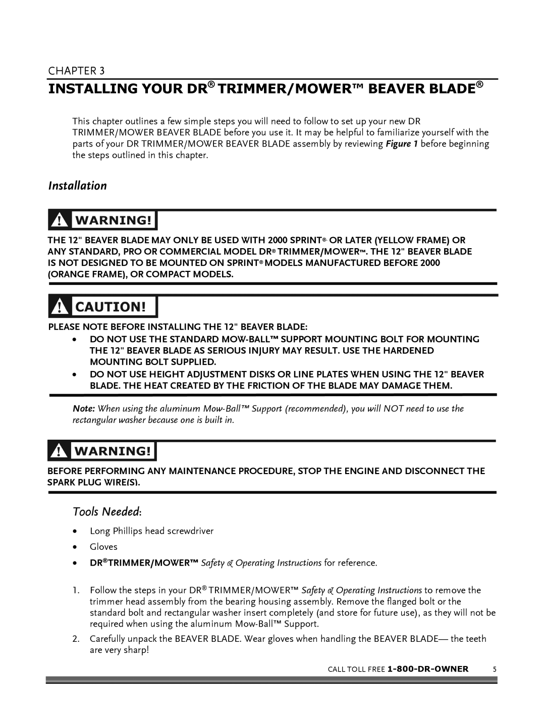
DR TRIMMER/MOWERTM BEAVER BLADE specifications
The Country Home Products DR TRIMMER/MOWER with BEAVER BLADE is a versatile piece of outdoor equipment designed for homeowners who need an efficient and effective solution for maintaining their lawns and gardens. This innovative machine combines the functionality of a trimmer and a mower, allowing users to tackle a wide range of landscaping tasks with ease.One of the standout features of the DR TRIMMER/MOWER is its powerful engine. Equipped with a reliable four-stroke engine, it delivers the torque necessary to handle thick grass, brush, and even small saplings. This power allows the machine to cut through tough vegetation effortlessly, making it a valuable tool for clearing overgrown areas and maintaining garden beds.
The BEAVER BLADE technology makes this trimmer/mower even more effective. The unique design of the blade consists of several tough, razor-sharp teeth that provide a clean cut while minimizing the risk of damage to the surrounding plants. This feature is particularly beneficial for users who need to trim around delicate landscaping features without harming them.
Another notable characteristic of the DR TRIMMER/MOWER is its adjustable cutting height. Users can easily modify the height of the cutting blade to accommodate different types of grass and terrain. Whether mowing a flat lawn or tackling uneven ground, this machine provides the flexibility needed to achieve precise results.
The ergonomic design of the trimmer/mower contributes to its ease of use. Its lightweight frame ensures maneuverability while reducing user fatigue during extended working sessions. The adjustable handles allow for comfortable operation, catering to users of different heights and preferences.
In addition to its powerful performance and user-friendly design, the DR TRIMMER/MOWER is built to withstand the rigors of outdoor work. Constructed from durable materials, it is designed to offer longevity and reliability throughout the seasons.
Safety is also a priority with this machine. It features safety guards that protect users from flying debris, making it a safe choice for trimming tasks in residential areas.
Overall, the Country Home Products DR TRIMMER/MOWER with BEAVER BLADE is an exceptional tool for homeowners. Offering power, versatility, and ease of use, it simplifies lawn care and landscaping, enabling users to maintain their properties with confidence and efficiency. Its innovative features make it a must-have for any serious gardener or landscaper.

