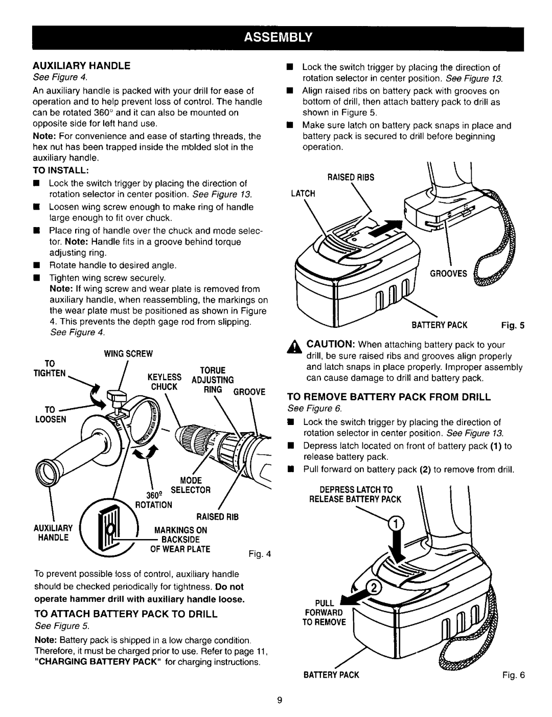
AUXILIARY HANDLE
See Figure 4.
An auxiliary handle is packed with your drill for ease of
operation and to help prevent loss of control. The handle can be rotated 360 ° and it can also be mounted on
opposite side for left hand use.
Note: For convenience and ease of starting threads, the hex nut has been trapped inside the mblded slot in the auxiliary handle.
TO INSTALL:
•Lock the switch trigger by placing the direction of rotation selector in center position. See Figure 13.
•Loosen wing screw enough to make ring of handle large enough to fit over chuck.
•Place ring of handle over the chuck and mode selec- tor. Note: Handle fits in a groove behind torque adjusting ring.
•Rotate handle to desired angle.
•Tighten wing screw securely.
Note: If wing screw and wear plate is removed from auxiliary handle, when reassembling, the markings on the wear plate must be positioned as shown in Figure
4.This prevents the depth gage rod from slipping. See Figure 4.
| WINGSCREW |
|
TO |
| TORUE |
|
| |
TIGHTEN | KEYLESS | ADJUSTING |
| CHUCK | RING GROOVE |
TO |
|
|
LOOSEN |
|
|
MODE
360_o SELECTOR
ROTATION
RAISEDRIB
AUXILIARYMARKINGSON
HANDLEBACKSIDE OF WEARPLATE
Fig. 4
To prevent possible loss of control, auxiliary handle
should be checked periodically for tightness. Do not
operate hammer drill with auxiliary handle loose.
TO ATTACH BATTERY PACK TO DRILL
See Figure 5.
Note: Battery pack is shipped in a low charge condition. Therefore, it must be charged prior to use. Refer to page 11, "CHARGING BATTERY PACK" for charging instructions.
•Lock the switch trigger by placing the direction of rotation selector in center position. See Figure 13.
•Align raised ribs on battery pack with grooves on bottom of drill, then attach battery pack to drill as shown in Figure 5.
•Make sure latch on battery pack snaps in place and battery pack is secured to drill before beginning operation.
RAISEDRIBS
LATCH
BATTERYPACK Fig, 5
CAUTION: When attaching battery pack to your drill, be sure raised ribs and grooves align properly
and latch snaps in place properly. Improper assembly can cause damage to drill and battery pack.
TO REMOVE BATTERY PACK FROM DRILL
See Figure 6.
•Lock the switch trigger by placing the direction of rotation selector in center position. See Figure 13.
•Depress latch located on front of battery pack (1) to release battery pack.
•Pull forward on battery pack (2) to remove from drill.
DEPRESSLATCHTO
RELEASEBATTERYPACK
PULL
FORWARD
TO REMOVE
BATTERYPACK | Fig. 6 |
9
