12. Assemble a lift rod trunnion (facing in) to each lift link rod using either a, b or c:
a. two
nut you removed earlier (models before 1995). c. a
you removed earlier (all other models)
The correct nuts will screw on easily. Tighten nuts so that one thread of rod extends past bottom nut.
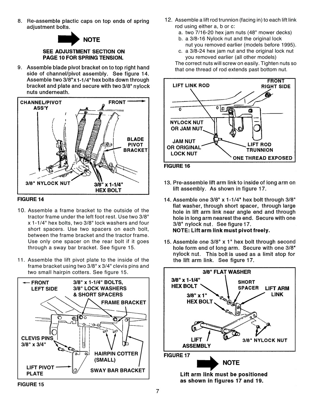
10. Assemble a frame bracket to the outside of the tractor frame under the left foot rest. Use two 3/8" x
11.Assemble the lift pivot plate to the inside of the frame bracket using two 3/8" x 3/4" clevis pins and two small hairpin cotters. See figure 15.
 FRONT LEFT SIDE
CLEVIS PINS 3/8" x 3/4" ![]()
3/8" x
FRAME BRACKET
HAIRPIN COTTER (SMALL)
LIFT PIVOT ![]()
PLATE
SWAY BAR BRACKET
FIGURE 15
7