GLOSSARY
Become familiar with these terms before operating the unit.
CFM: Cubic feet per minute.
SCFM: Standard cubic feet per minute; a unit of measure of air delivery.
PSIG: Pounds per square inch gauge; a unit of meas- ure of pressure.
Code Certification: Products that bear one or more
of the following marks: UL, CUL, ETL, CETL, have been evaluated by OSHA certified independent safety laboratories and meet the applicable Underwriters Laboratories Standards for Safety.
Branch Circuit: Circuit carrying electricity from elec- trical panel to outlet.
ACCESSORIES
This unit is capable of powering the following Accessories. The accessories are available through the current Power and Hand Tool Catalog or
Accessories
•In Line Filter
•Tire Air Chuck
•Quick Connector Sets (various sizes)
•Air Pressure Regulators
•Oil Fog Lubricators
•Air Hose:
1/4", 5/16" OR 3/8" I.D. in various lengths
Specialty Tools | Socket Driving | ||
• | Air Brush | • | 3/8" Impact/Butterfly Wrench |
• | Inflating/Blow Gun | • | 3/8" Ratchet |
• | Grease Gun | • | 1/4" Ratchet |
• | Caulk Gun | Material Shaping | |
• | Engine Cleaner | • | 2.625" Hammer |
Carpentry Tools | • | 1.625" Hammer | |
• Finishing Nailer / Stapler | • | Reciprocating Saw | |
• Construction Nailer / Stapler | • | Nibbler | |
|
| Spray Painting | |
|
| • | |
|
| • | Automotive Spray Gun |
ASSEMBLY
Contents of Carton
1 - Air Compressor
4 - Rubber Feet
1 - 3/8” x 25’ Hose
1 - Brad Nailer
2 - 1/4” Quick Connect Body
2 - 1/4’ Quick Connect Plug
1 - Roll of Teflon Tape
Tools Required for Assembly
1 - 3/8” socket or nut driver
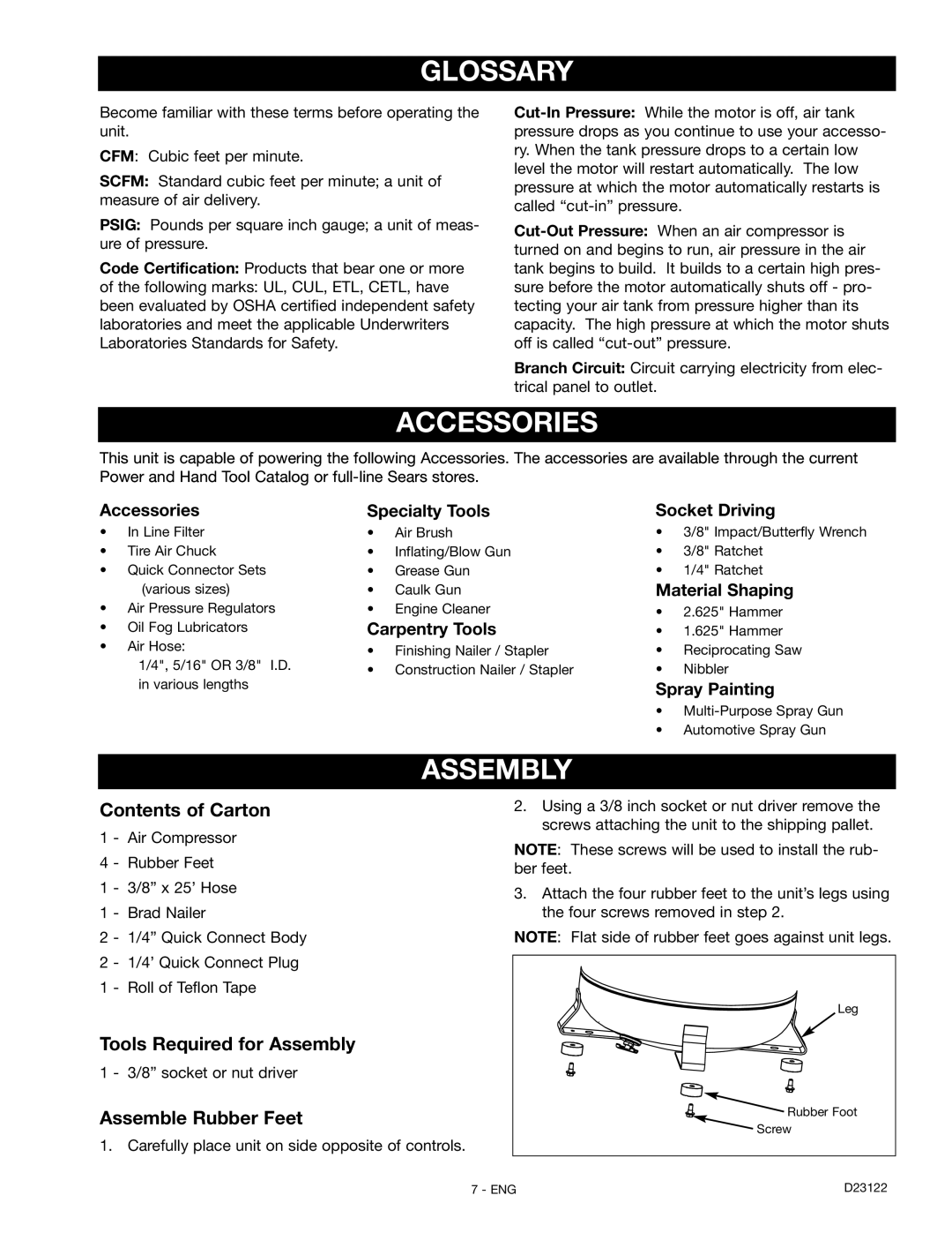
Assemble Rubber Feet
1. Carefully place unit on side opposite of controls.
2.Using a 3/8 inch socket or nut driver remove the screws attaching the unit to the shipping pallet.
NOTE: These screws will be used to install the rub- ber feet.
3.Attach the four rubber feet to the unit’s legs using the four screws removed in step 2.
NOTE: Flat side of rubber feet goes against unit legs.
| Leg |
| Rubber Foot |
| Screw |
7 - ENG | D23122 |