CARTON CONTENTS
Check carton contents against the foF lowing list,
Model 0944.511572
•Edger attachment
•Handlebar
•Handlebar mounting bracket for 1" (2.5 cm) shaft
•Handlebar mounting bracket for 7/8" (2.2 cm) shaft
•Bracket cover (2)
•Handlebar bracket screws (4)
•Attachment Hanger
•Hex Wrench
Examine parts for damage. Do not use damaged parts.
NOTE: If you need assistance or find parts missing or damaged, call
ASSEMBLY
_WARNING: | If received as- |
sembled, repeat all steps to ensure
_/aOUrunit is properly assembled and all steners are secure.
• A hex wrench (provided) is required for assembly,
HANDLEBAR ASSEMBLY
DANGER: RISK OF CUT, To
avoid serious injury, the barrier portion of the handlebar must be installed as
shown on the upper shaft of the pew- erheed to provide a barrier between operator and the spinning blade. At- tach handlebar mounting bracket above arrow on safety warning decal on the upper shaft (pewerhead end of unit). Ensure handlebar is positioned on mounting bracket at the end of the arrow on the handlebar decal,
NOTE: Two mounting brackets are in- cluded with this attachment. Both brack-
ets are provided to adapt this attach- ment for use with powerheads that have either a 1" (2.5 cm) diameter or a 7/8" (2.2 cm) diameter upper shaft. The cor- rect bracket must be used to ensure that the handlebar is mounted securely to the upper shaft before use,
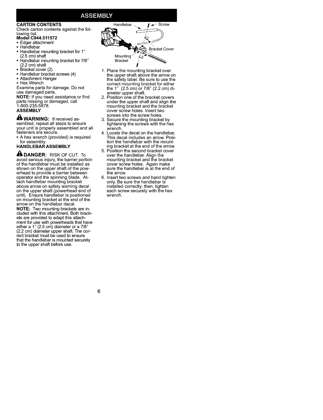
Handlebar _. | _ |
_ | Bracket Cover |
Mounting | _.._ |
Bracket | !,' |
1.Place the mounting bracket over the upper shaft above the arrow on the safety label. Be sure to use the correct mounting bracket for either the 1" (2.5 cm) or 7/8" (2.2 cm) di- ameter upper shaft.
2.Position one of the bracket covers under the upper shaft and align the mounting bracket and the bracket cover screw holes. Insert two screws into the screw holes.
3.Secure the mounting bracket by
tightening the screws with the hex wrench.
4.Locate the decal on the handlebar. This decal includes an arrow. Posi- tion the handlebar with the mount- ing bracket at the end of the arrow.
5.Position the second bracket cover over the handlebar. Align the mounting bracket and the bracket
cover screw holes. Again make sure the handlebar is at the end of the arrow.
6.Insert two screws and hand tighten only. Be sure the handlebar is installed correctly; then, tighten
each screw securely with the hex wrench.
6