VC-6112/6210/6212 Amplifier
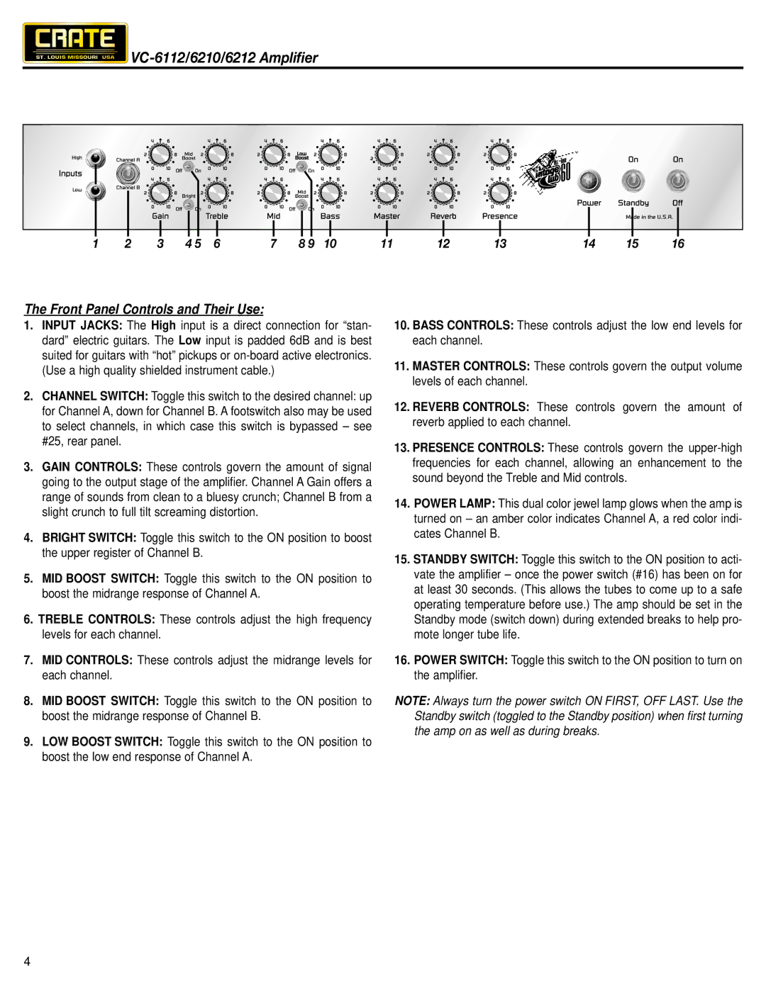
1 | 2 | 3 | 4 5 | 6 | 7 | 8 9 | 10 | 11 | 12 | 13 | 14 | 15 | 16 |
The Front Panel Controls and Their Use:
1.INPUT JACKS: The High input is a direct connection for “stan- dard” electric guitars. The Low input is padded 6dB and is best suited for guitars with “hot” pickups or
2.CHANNEL SWITCH: Toggle this switch to the desired channel: up for Channel A, down for Channel B. A footswitch also may be used to select channels, in which case this switch is bypassed – see #25, rear panel.
3.GAIN CONTROLS: These controls govern the amount of signal going to the output stage of the amplifier. Channel A Gain offers a range of sounds from clean to a bluesy crunch; Channel B from a slight crunch to full tilt screaming distortion.
4.BRIGHT SWITCH: Toggle this switch to the ON position to boost the upper register of Channel B.
5.MID BOOST SWITCH: Toggle this switch to the ON position to boost the midrange response of Channel A.
6.TREBLE CONTROLS: These controls adjust the high frequency levels for each channel.
7.MID CONTROLS: These controls adjust the midrange levels for each channel.
8.MID BOOST SWITCH: Toggle this switch to the ON position to boost the midrange response of Channel B.
9.LOW BOOST SWITCH: Toggle this switch to the ON position to boost the low end response of Channel A.
10.BASS CONTROLS: These controls adjust the low end levels for each channel.
11.MASTER CONTROLS: These controls govern the output volume levels of each channel.
12.REVERB CONTROLS: These controls govern the amount of reverb applied to each channel.
13.PRESENCE CONTROLS: These controls govern the
14.POWER LAMP: This dual color jewel lamp glows when the amp is turned on – an amber color indicates Channel A, a red color indi- cates Channel B.
15.STANDBY SWITCH: Toggle this switch to the ON position to acti- vate the amplifier – once the power switch (#16) has been on for at least 30 seconds. (This allows the tubes to come up to a safe operating temperature before use.) The amp should be set in the Standby mode (switch down) during extended breaks to help pro- mote longer tube life.
16.POWER SWITCH: Toggle this switch to the ON position to turn on the amplifier.
NOTE: Always turn the power switch ON FIRST, OFF LAST. Use the Standby switch (toggled to the Standby position) when first turning the amp on as well as during breaks.
4