VC-6112/6210/6212 Amplifier
TO REPLACE THE RISK OF FIRE,
REPLACE FUSE WITH SAME TYPE
AND RATING.
UTILISER UN FUSIBLE DE RECHANGE
DE MEME TYPE.
AC LINE IN
100 / 120 VAC | 250V, T2.5A SLO BLO |
220 / 240 VAC | 250V, T1.5A SLO BLO |
BIAS | |
ADJUST | T.P. |
NOTE: BIAS ADJUSTMENT | |
SHOULD BE | PERFORMED |
ONLY BY QUALIFIED SERVICE | |
TECHNICIAN. |
|
IMPEDANCE
SELECTOR
16 8
SPEAKERS | |
60 WATTS RMS | |
SPEAKER IMPEDANCE MUST MATCH | |
SELECTED AMPLIFIER IMPEDANCE | |
MAIN | EXT. |
(USE FIRST) |
|
| EFFECTS LOOP |
|
|
|
|
| RETURN | SEND | FOOTSWITCH |
| |
0 | 10 |
| R |
|
|
EFFECTS LEVEL |
| S R | T | ||
| T | ||||
| S TIP = CH. SELECT |
| |||
|
|
|
| ||
|
|
| RING = LOOP ON/OFF |
| |
|
|
| SLEEVE = GROUND |
| |
MODEL: |
| ||
SERIAL: | |||
MODEL |
| Hz | |
LINE: |
| V ~ | |
WATTS: |
| MAX |
|
SERIAL # | A |
| |
MADE IN THE U.S.A. BY SLM ELECTRONICS 1400 FERGUSON AVENUE, ST. LOUIS, MO 63133
CAUTION
RISK OF ELECTRIC SHOCK
DO NOT OPEN
AVIS: RISQUE DE CHOC ELECTRIQUE. NE PAS OUVRIR.
WARNING: TO REDUCE THE RISK OF FIRE OR ELECTRIC SHOCK, DO NOT EXPOSE THIS APPLIANCE TO RAIN OR
MOISTURE.
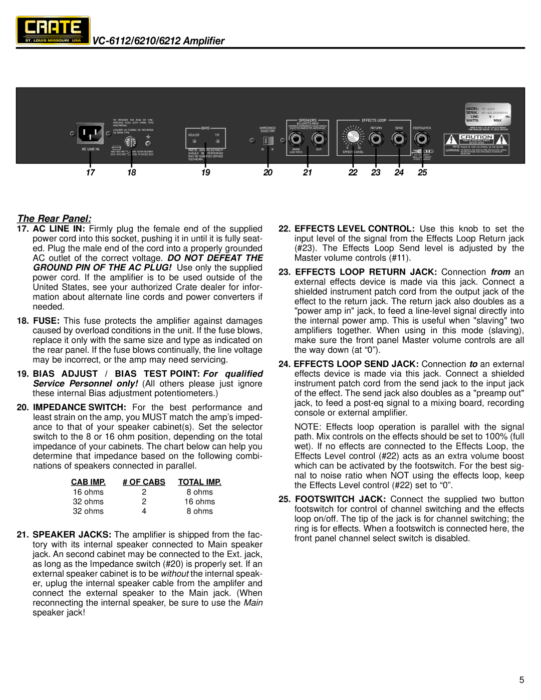
17 | 18 | 19 | 20 | 21 | 22 | 23 | 24 | 25 |
The Rear Panel:
17.AC LINE IN: Firmly plug the female end of the supplied power cord into this socket, pushing it in until it is fully seat- ed. Plug the male end of the cord into a properly grounded AC outlet of the correct voltage. DO NOT DEFEAT THE GROUND PIN OF THE AC PLUG! Use only the supplied power cord. If the amplifier is to be used outside of the United States, see your authorized Crate dealer for infor- mation about alternate line cords and power converters if needed.
18.FUSE: This fuse protects the amplifier against damages caused by overload conditions in the unit. If the fuse blows, replace it only with the same size and type as indicated on the rear panel. If the fuse blows continually, the line voltage may be incorrect, or the amp may need servicing.
19.BIAS ADJUST / BIAS TEST POINT: For qualified Service Personnel only! (All others please just ignore these internal Bias adjustment potentiometers.)
20.IMPEDANCE SWITCH: For the best performance and least strain on the amp, you MUST match the amp’s imped- ance to that of your speaker cabinet(s). Set the selector switch to the 8 or 16 ohm position, depending on the total impedance of your cabinets. The chart below can help you determine that impedance based on the following combi- nations of speakers connected in parallel.
CAB IMP. | # OF CABS | TOTAL IMP. |
16 ohms | 2 | 8 ohms |
32 ohms | 2 | 16 ohms |
32 ohms | 4 | 8 ohms |
21.SPEAKER JACKS: The amplifier is shipped from the fac- tory with its internal speaker connected to Main speaker jack. An second cabinet may be connected to the Ext. jack, as long as the Impedance switch (#20) is properly set. If an external speaker cabinet is to be without the internal speak- er, uplug the internal speaker cable from the amplifer and connect the external speaker to the Main jack. (When reconnecting the internal speaker, be sure to use the Main speaker jack!
22.EFFECTS LEVEL CONTROL: Use this knob to set the input level of the signal from the Effects Loop Return jack (#23). The Effects Loop Send level is adjusted by the Master volume controls (#11).
23.EFFECTS LOOP RETURN JACK: Connection from an external effects device is made via this jack. Connect a shielded instrument patch cord from the output jack of the effect to the return jack. The return jack also doubles as a "power amp in" jack, to feed a
24.EFFECTS LOOP SEND JACK: Connection to an external effects device is made via this jack. Connect a shielded instrument patch cord from the send jack to the input jack of the effect. The send jack also doubles as a "preamp out" jack, to feed a
NOTE: Effects loop operation is parallel with the signal path. Mix controls on the effects should be set to 100% (full wet). If no effects are connected to the Effects Loop, the Effects Level control (#22) acts as an extra volume boost which can be activated by the footswitch. For the best sig- nal to noise ratio when NOT using the effects loop, keep the Effects Level control (#22) set to “0”.
25.FOOTSWITCH JACK: Connect the supplied two button footswitch for control of channel switching and the effects loop on/off. The tip of the jack is for channel switching; the ring is for effects. When a footswitch is connected here, the front panel channel select switch is disabled.
5